


Quick Research
Generate reliable direction feasibility study reports for your R&D in just a few steps.

Technical Q&A
Discover and master advanced knowledge NOW. Basics, ideas, possibilities, all at once.

Find Solutions
As an expert in R&D theories, this can generate solutions to your technical problems instantly.

Evaluate Feasibility
Analyze your overall solution with one click, know your potential R&D risks in advance.

Monitor Landscape
Get weekly tech updates, stay abreast of the latest tech innovations and key insights.
Cutting apparatus, tray, and transport system
A cutting device and pallet technology, applied in the field of conveying systems, can solve the problem of wasting time and achieve the effect of efficient loading and unloading
- Summary
- Abstract
- Description
- Claims
- Application Information
AI Technical Summary
Problems solved by technology
Method used
Image

Examples
no. 1 Embodiment approach
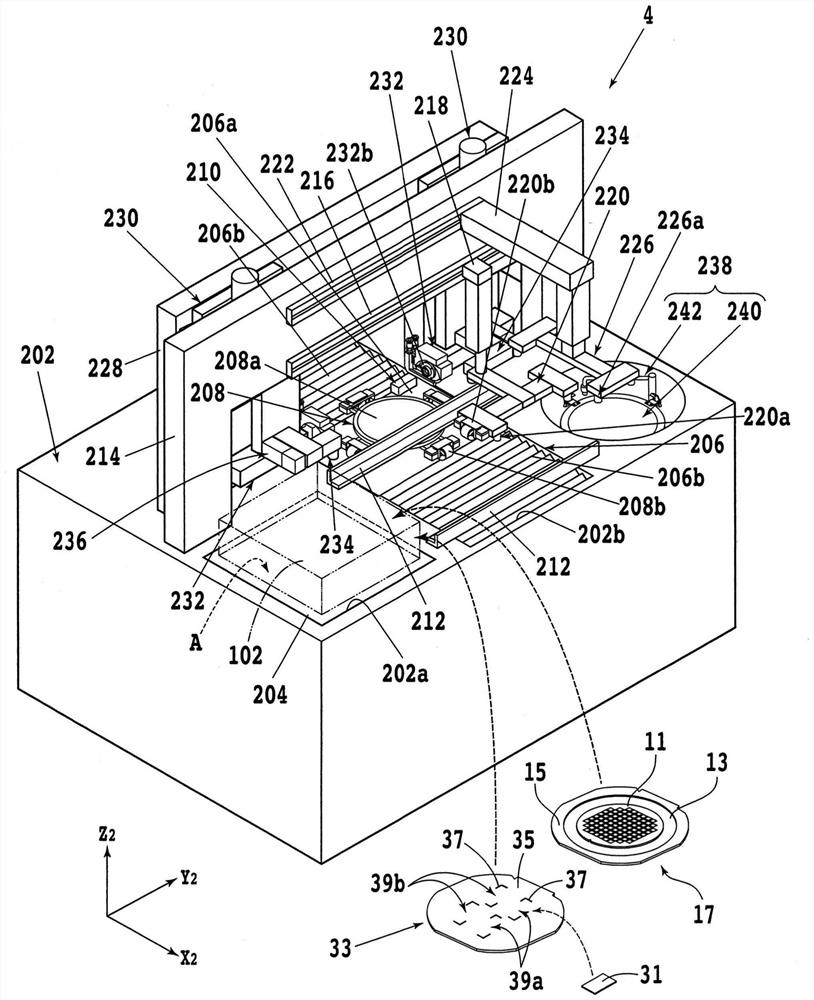
[0051] figure 1 It is a perspective view showing the internal structure of a processing device (cutting device) 4 for processing (cutting) a plate-shaped workpiece 11 . Also, the X used in the following descriptions 2 Axis direction, Y 2 Axis direction and Z 2 The axis directions are approximately perpendicular to each other. Such as figure 1 As shown, the processing apparatus 4 has a base 202 that supports each component.
[0052] A recessed portion 202a is formed at a corner of the base 202, and an elevating table 204 that is raised and lowered by an elevating mechanism (not shown) is disposed in the recessed portion 202a. For example, a container (cassette) 102 of a transport vehicle 10 , which will be described later, capable of storing a workpiece 11 , a plate 31 , and the like, is placed in a loading area A on the upper surface of the lift table 204 . In addition, a plurality of position limiting members (not shown) for limiting the horizontal position of the conta...
no. 2 Embodiment approach
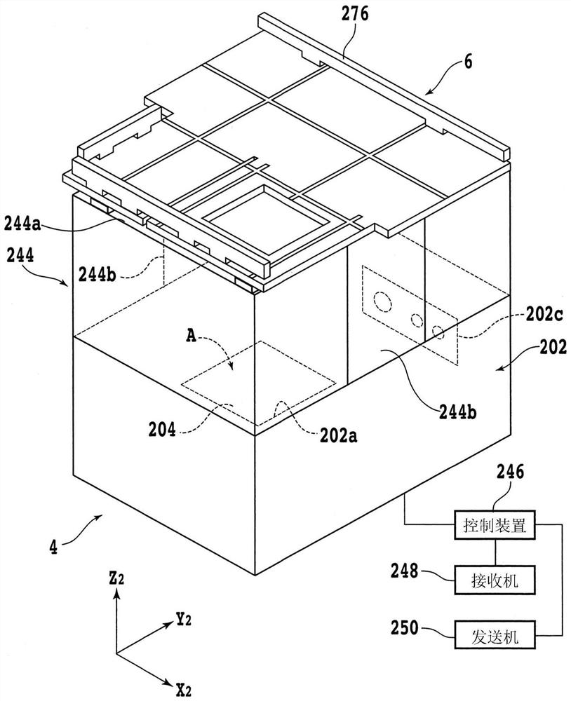
[0417] In this embodiment, a processing device (cutting device) in a mode different from the above-described embodiment will be described. Figure 35 It is a perspective view showing the internal structure of the processing device (cutting device) 402 of this embodiment. In addition, in the following description, the same code|symbol is attached|subjected to the component common to the said embodiment, and detailed description is abbreviate|omitted.
[0418] The container 102 of the transport vehicle 10 is not placed on the lift table 404 of the processing device 402 . Instead, on the elevating table 404 of the processing device, the same two-stage cassette storage mechanism 24 (that is, the first cassette storage mechanism 24a and the second cassette storage mechanism 24b) as the loader / unloader 8 of the above-mentioned embodiment is provided. Two-stage cassette storage mechanism 406 (1st cassette storage mechanism 406a and 2nd cassette storage mechanism 406b).
[0419] Tha...
PUM
 Abstract
Description
Claims
Application Information
 - R&D Engineer
- R&D Manager
- IP Professional
- Industry Leading Data Capabilities
- Powerful AI technology
- Patent DNA Extraction
Browse by: Latest US Patents, China's latest patents, Technical Efficacy Thesaurus, Application Domain, Technology Topic, Popular Technical Reports.
© 2024 PatSnap. All rights reserved.Legal|Privacy policy|Modern Slavery Act Transparency Statement|Sitemap|About US| Contact US: help@patsnap.com