
Highway bridge damping and buffering support

A technology for highway bridges and shock absorbers, which is applied in bridges, bridge construction, bridge parts, etc., can solve problems such as cracking and voiding, small deformation capacity, and abnormal deformation of bearings.

Pending Publication Date: 2021-10-08
何小林
View PDF6 Cites 0 Cited by
  • Summary
  • Abstract
  • Description
  • Claims
  • Application Information

AI Technical Summary

Problems solved by technology

[0003] However, there are still deficiencies in the existing bearings, for example, the bearings are prone to abnormal deformation, cracking and voiding, and at the same time, the deformation capacity is small, which cannot meet the needs of the angle change of large bridges

Method used


Image

  • Highway bridge damping and buffering support
  • Highway bridge damping and buffering support
  • Highway bridge damping and buffering support

Examples


Embodiment 1

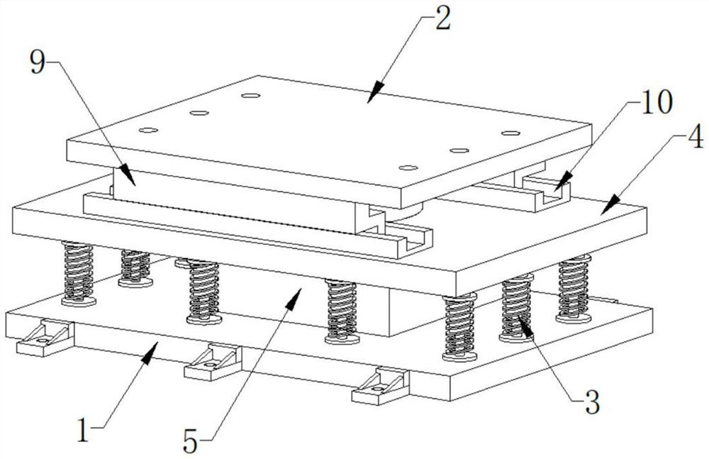
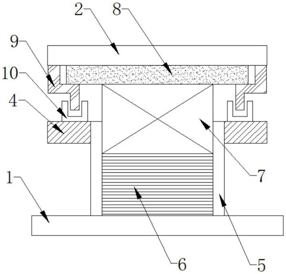
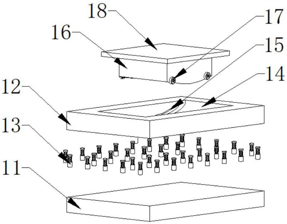
[0022] Such as Figure 1-3 As shown, the present invention provides a road bridge damping buffer bearing, comprising a lower steel plate 1 and an upper steel plate 2, the top surface of the lower steel plate 1 is surrounded by a plurality of first spring struts 3, and the first spring struts 3 The top is connected with a partition 4, and a dust cover 5 is installed in the middle of the top surface of the lower steel plate 1, and the top of the dust cover 5 penetrates the partition 4, and the inside of the dust cover 5 is embedded with a buffer base 6, and the top of the buffer base 6 A shock absorbing device 7 is provided, the top of the shock absorbing device 7 is connected with a slide plate 8, and the front and rear sides of the bottom surface of the upper steel plate 2 are provided with relative limit flaps 9, and the slide plate 8 is located between the limit fold plates 9 , The bottom end of the limiting flap 9 is provided with a groove seat 10 .

[0023] Further, the d...

Embodiment 2

[0029] This embodiment and embodiment 1 are only improved on the shock absorber 7, and other places can be the same; further, the shock absorber 7 includes a circular base 19 and a support ball core 20, and the support ball core 20 is a hemispherical structure. And the bottom surface is provided with a spherical PTFE plate 21, the top surface of the circular base 19 has a container 22, and the spherical PTFE plate 21 is placed inside the container 22, and the volume of the supporting ball core 20 is greater than that of the container 22. volume, the top surface of the supporting ball core 20 is provided with a top plate 23, a plurality of third spring struts 24 are connected between the top surface of the top plate 23 and the circular base 19, and the top end of the top plate 23 is connected with the slide plate 8

[0030] Specifically, after the shock absorber 7 is vibrated by force, the top plate 23 shifts to one side and then drives the supporting ball core 20 to shift, and ...


PUM


Abstract

The invention discloses a highway bridge damping and buffering support which comprises a lower steel plate and an upper steel plate, a plurality of first spring supporting rods are arranged on the surface of the top end of the lower steel plate in a surrounding mode, the top ends of the first spring supporting rods are connected with a partition plate, a dust cover is installed in the middle of the surface of the top end of the lower steel plate, and a buffering base is embedded in the dust cover; a damping device is arranged at the top end of the buffering base, a sliding plate is connected to the top end of the damping device, opposite limiting folded plates are arranged on the front side and the rear side of the bottom end surface of the upper steel plate, and groove bases are arranged at the bottom ends of the limiting folded plates. Sufficient bearing capacity in the vertical direction is provided for the support through the buffering base, large-amplitude vibration around the support can be preliminarily absorbed through the first spring supporting rods, vibration inside the support can be absorbed through the damping devices, good elasticity is achieved, the support can adapt to rotation of the bridge end, meanwhile, the damping devices have enough deformation capacity, and the displacement of the upper bridge structure is met.

Description

technical field [0001] The invention relates to the field of bridges, in particular to a shock-absorbing buffer bearing for a highway bridge. Background technique [0002] The bridge support is an important structural component connecting the upper structure and the lower structure of the bridge. The bridge support is erected on the abutment, and the top surface supports the upper structure of the bridge. Its function is to fix the upper structure to the abutment and bear the force acting on the upper structure. Various forces, and reliably transmit it to the pier, under the action of load, temperature, concrete shrinkage and creep, the support can adapt to the rotation angle and displacement of the superstructure, so that the superstructure can be freely deformed without additional additional internal force. [0003] However, there are still deficiencies in the existing bearings, for example, the bearings are prone to abnormal deformation, cracking and voiding, and the def...

Claims


Application Information

Patent Timeline
IPC IPC(8): E01D19/04
CPCE01D19/041E01D19/046
Inventor 何小林
Owner 何小林
Learn More