
Method for manufacturing a stiffened panel made from composite material

a composite material and stiffening technology, applied in the field of stiffening panels, can solve the problems of high weight penalties and/or high production and assembly costs, and increase recurring costs and lead time, and achieve the effect of reducing labor hours and reducing recurring costs

Active Publication Date: 2017-08-10
AIRBUS DEFENCE & SPACE
View PDF7 Cites 1 Cited by
  • Summary
  • Abstract
  • Description
  • Claims
  • Application Information

AI Technical Summary

Benefits of technology

The invention is about improving the deformability of the crosses of pre-preg elongated reinforcing elements during the forming cycle of a panel. This is achieved by laying up a single flat laminate comprising all the reinforcing elements and cutting corners of the reinforcing elements' crosses to acquire enough deformability. This results in a faster machining speed, reduces recurring costs and lead time, and requires only one hot forming process. The invention also integrates reinforcing elements in one single laminate, reducing recurring costs and labor hours during assembly operations.

Problems solved by technology

This process has the drawback that one or two laminates are needed to get every longitudinal reinforcing element, increasing recurring costs and lead time.
This implies that both elements shall be thereafter joined in the crossing zones by a plurality of connecting elements (riveted or bonded), resulting in high weight penalties and / or high production and assembly costs and also debonding risks when using connecting elements bonded to the beams and frames.
However, it is a challenge to solve the composites core with efficient stiffness and easy manufacturing.

Method used


Image

  • Method for manufacturing a stiffened panel made from composite material
  • Method for manufacturing a stiffened panel made from composite material
  • Method for manufacturing a stiffened panel made from composite material

Examples


Embodiment Construction

[0042]FIG. 1 shows a known process for manufacturing a stiffened panel and

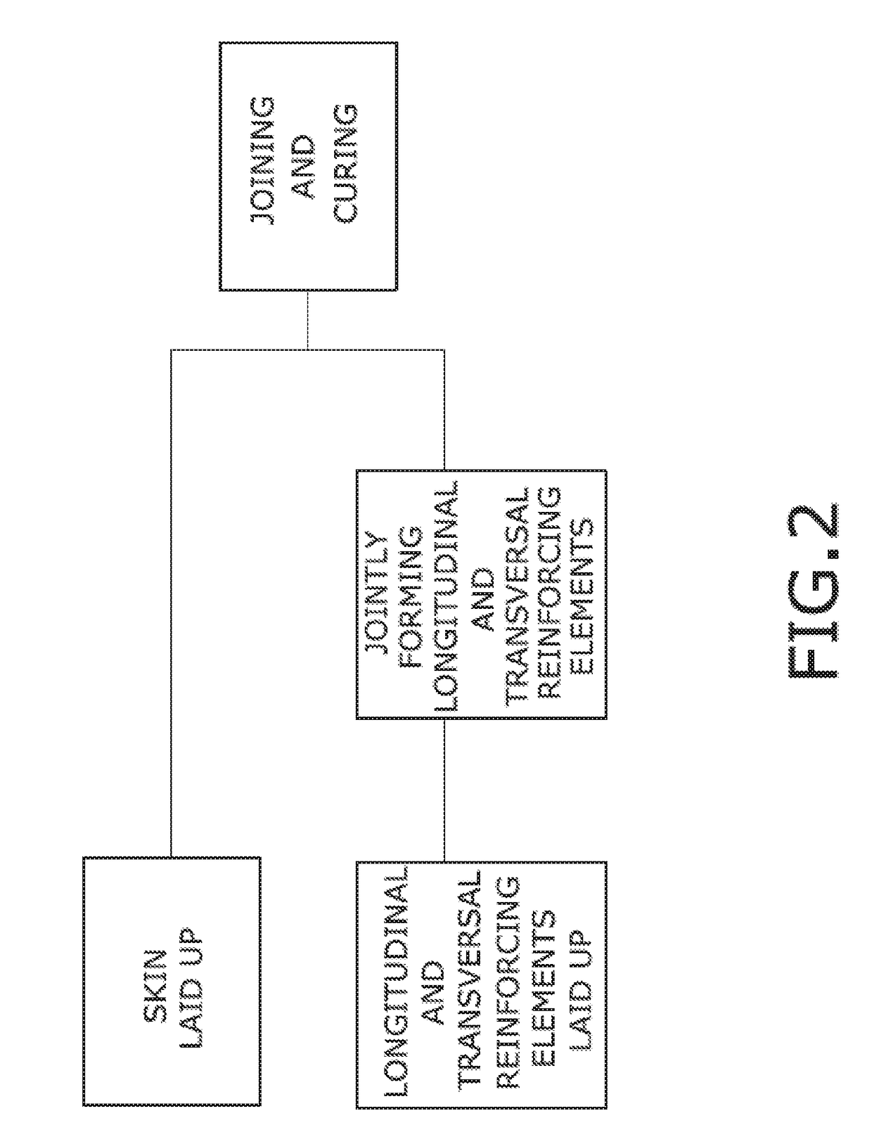
[0043]FIG. 2 shows an embodiment of the claimed process.

[0044]FIG. 3 shows a perspective view of an embodiment of a stiffened panel comprising a skin (1) and elongated reinforcing elements (2, 3), particularly longitudinal and transversal straight omega stringers (2, 3) although other configurations would be possible, such as curved beams or frames crossing with stringers at an angle different than 90°.

[0045]The stringers (2, 3) have a closed shape cross section (omega Ω-shaped or even variants thereof) with a head (20), two webs (21) and two opposite longitudinal flanges (22) which are fixed onto a face of the skin (1).

[0046]In the shown embodiment, both the stringer (2, 3) laminate and the skin (1) laminate are made of pre-preg. Both flat laminates are manufactured by an Automated Tape Layup (ATL) machine.

[0047]Regarding the stringers (2, 3), the result of the two first steps of the claimed method is depicte...


PUM

PropertyMeasurementUnit
angleaaaaaaaaaa
shapeaaaaaaaaaa
structureaaaaaaaaaa

Abstract

A method for manufacturing a stiffened panel made from composite material comprising a skin and elongated reinforcing elements wherein some of the elongated reinforcing elements cross each other. The method comprises the steps of (a) laying up a flat laminate comprising stacked plies of composite layers for forming a structure comprising the elongated reinforcing elements of the panel, (b) cutting the flat laminate along intersection lines of planes defining the webs of two crossing reinforcing elements, (c) cutting in the flat laminate the outline of the elongated reinforcing elements, (d) forming the structure comprising the elongated reinforcing elements of the panel, (e) laying up plies of composite layers for forming the skin, and (f) curing the laid-up plies of the skin and the formed structure comprising the elongated reinforcing elements.

Description

CROSS-REFERENCES TO RELATED APPLICATIONS[0001]This application claims the benefit of the European patent application No. 16382052.5 filed on Feb. 9, 2016, the entire disclosures of which are incorporated herein by way of reference.FIELD OF THE INVENTION[0002]The present invention refers to a method for manufacturing integral monolithic structures made from composite material. More specifically, the invention refers to the manufacture of the so-called stiffened panels made from composite material including a skin and a series of elongated reinforcing elements, for instance, stringers, beams or frames, which are fixed onto a face of the skin.[0003]The invention is intended to be applied in the field of aeronautics, in particular, but not exclusively, for fuselage panels but also for wing and tail panels and other applications.BACKGROUND OF THE INVENTION[0004]Currently, panels of carbon fiber reinforced polymers (CFRP) are stiffened with longitudinal reinforcing elements of different s...

Claims


Application Information

Patent Timeline
Patent Type & Authority Applications(United States)
IPC IPC(8): B29C70/34B29C70/54B29C70/38
CPCB29C70/34B29C70/386B29C70/54B29K2105/06B29L2031/3085B29K2995/0082B29L2009/00B29L2031/3082B29K2307/04B29D99/0014
Inventor NOGUEROLES VINES, PEDROCUENCA RINCON, JOSEGARCIA GARCIA, AQUILINOLOPEZ ROMANO, BERNARDOMORA MENDIAS, MARIA
Owner AIRBUS DEFENCE & SPACE
Learn More