
Grinding machine tool device for metal blank

A blank and grinding technology is applied to the field of grinding machine tools for metal blanks, and can solve the problems of troublesome processing of metal blanks, slow down of burrs and the like.

Active Publication Date: 2021-09-17
苏州辉荣合升机械制造有限公司
View PDF9 Cites 0 Cited by
  • Summary
  • Abstract
  • Description
  • Claims
  • Application Information

AI Technical Summary

Problems solved by technology

[0003] For existing automotive disc-shaped parts, such as brake discs, or disc-shaped valves, the outer arc surface is used as the working surface, and the smoothness of the workpiece surface needs to be maintained. Therefore, in the corresponding disc-shaped metal blanks Grinding is carried out at the arc surface of the disc. When grinding the disc metal blank, the workpiece is fixed on one end of the processing table, and the grinding equipment is set on the outside, and the grinding equipment moves around the metal blank. , to achieve rotational grinding, after the cutting edge part of the grinding equipment contacts the burrs on the surface of the metal blank, the burrs are cut off, because the grinding equipment performs grinding along the arc surface, and the burrs under cutting are along the arc surface The burr under cutting has a certain high temperature. At the same time, under the high-speed contact between the grinding equipment and the metal blank, the surface of the metal blank also has high temperature. When the high-temperature burr under cutting contacts the high-temperature metal blank along the arc surface On the surface of the workpiece, under the influence of thermal stress, the burr slides on the arc surface and slows down, causing corresponding impressions and residual stress on the surface of the metal blank. At present, it is necessary to regrind the surface of the workpiece after grinding to give the metal blank The processing of workpieces has brought troubles, for this reason, we propose a grinding machine tool device for metal blanks

Method used


Image

  • Grinding machine tool device for metal blank
  • Grinding machine tool device for metal blank
  • Grinding machine tool device for metal blank

Examples


Embodiment Construction

[0030] The following will clearly and completely describe the technical solutions in the embodiments of the present invention with reference to the accompanying drawings in the embodiments of the present invention. Obviously, the described embodiments are only some, not all, embodiments of the present invention. Based on the embodiments of the present invention, all other embodiments obtained by persons of ordinary skill in the art without making creative efforts belong to the protection scope of the present invention.

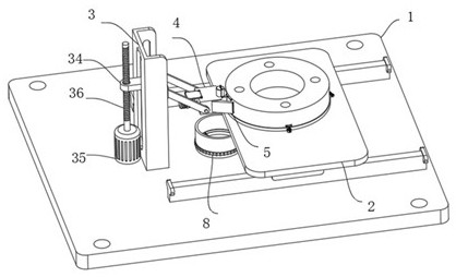
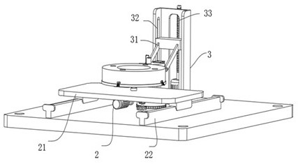
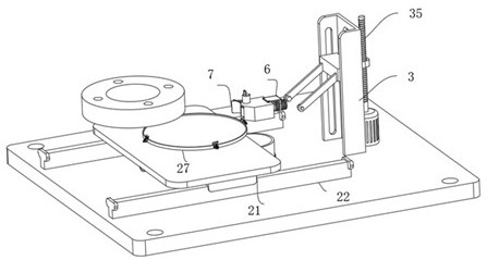
[0031] see Figure 1-13, the present invention provides a technical solution: a grinding machine tool device for metal blanks. This solution solves the problem that when the existing disc-shaped metal blanks are ground, the grinding burrs contact with the arc surface, resulting in the need to The surface of the arc-shaped workpiece is repeatedly processed. In this plan, the design includes a processing table 1. The four corners of the processing table 1 are pr...


PUM


Abstract

The invention discloses a grinding machine tool device for a metal blank. The grinding machine tool device comprises a machining table, wherein a rotating assembly is connected to the top of the machining table, a grinding shell is connected to one end of an adjusting support, an arc notch and an arc pressing plate are arranged at one end of the grinding shell, and a cutting guide shell is connected to the outer side of the grinding shell; and the grinding shell is connected with a driving assembly, the outer side of the driving assembly is connected with a dragging part, a discharging port is formed in the bottom of the grinding shell, and the machining table is connected with a collecting part. According to the grinding machine tool device for the metal blanks, the rotating assembly is used for driving a workpiece to be cut along the cutting edge of the cutting guide shell, cutting waste enters the cavity of the grinding shell and is dragged and collected to the collecting part through the dragging part to be collected and treated; and due to the fact that one end of the driving assembly and the arc pressing plate are subjected to press fit treatment, and meanwhile the cutting waste is collected through the dragging part, the cutting waste and a machining face are separated in the cutting process, and meanwhile press fit treatment is conducted on the machining face.

Description

technical field [0001] The invention relates to the technical field of metal processing equipment, in particular to a grinding machine tool device for metal blanks. Background technique [0002] Metal materials become metal blanks after being processed by stamping, forging, rolling and other mechanical processing methods. After preliminary results, the metal blanks meet the basic size requirements of the workpiece, but there are many defects on its surface. For metal cutting workpieces In other words, in addition to satisfying the function of the product and being able to meet its decoration, corrosion resistance, electrical conductivity and other performance requirements through subsequent processing, it is also hoped that it can have good cutting processing characteristics. In order to improve the surface of the metal blank When roughness and other requirements are required, the burrs on the surface of the metal blank are ground by grinding equipment. [0003] For existin...

Claims


Application Information

Patent Timeline
Patent Type & Authority Applications(China)
IPC IPC(8): B24B9/04B24B55/06B24B41/06B24B27/02B24B55/00B24B55/02B24B41/02
CPCB24B9/04B24B55/06B24B41/06B24B27/02B24B55/00B24B55/02B24B41/02
Inventor 李忠友李明朱晓星
Owner 苏州辉荣合升机械制造有限公司
Learn More