A CNC machine tool for processing large transmission gears
A technology of CNC machine tools and transmission gears, which is used in metal processing machinery parts, metal processing equipment, presses, etc., can solve the problems of scattered debris, large space occupation, inconvenient use and disposal, etc. The effect of taking up space and being easy to handle
- Summary
- Abstract
- Description
- Claims
- Application Information
AI Technical Summary
Problems solved by technology
Method used
Image
Examples
Embodiment 1
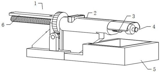
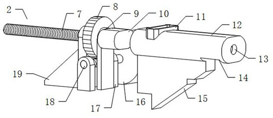
[0031] see Figure 1-2, an embodiment provided by the present invention: a large-scale transmission gear processing CNC machine tool, including a CNC machine tool scrap discharge device 1, a CNC machine tool scrap discharge device 1 includes a scrap compaction main body 2, and the scrap compaction body 2 includes Motor 16, motor 16 is electrically connected through an external power supply, CNC machine tool scrap discharge device 1 also includes discharge valve 3, delay body 4, base 5 and limiter body 6, scrap compaction body 2 and base 5 are fixedly installed together , the discharge valve 3 is slidably installed with the crushing body 2, the delay body 4 is fixedly connected with the crushing body 2, and the discharge valve 3 and the delaying body 4 are slidingly socketed and matched; the crushing body 2 also includes threads Rod 7, worm wheel 8, first bearing seat 9, extrusion slide block 10, feed inlet 11, compression cylinder 12, discharge hole 14, support frame 15, secon...
Embodiment 2
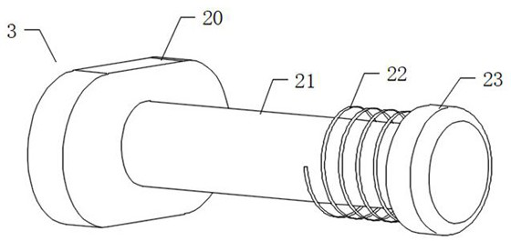
[0035] see image 3 , an embodiment provided by the present invention: the discharge valve 3 includes a valve plate 20, a slide rod 21, a tension spring 22 and a piston 23, the valve plate 20 is slidably installed on the inner wall of the compression cylinder 12, and the slide rod 21 is slidably installed on the guide hole 13 The inner wall of the sliding rod 21 runs through the guide hole 13, the valve plate 20 is fixedly connected with the sliding rod 21 as a whole, one end of the tension spring 22 is fixedly connected with the compression cylinder 12, and the other end of the tension spring 22 is fixedly connected with the piston 23, sliding The end of the rod 21 facing away from the valve plate 20 is fixedly installed with the piston 23, and the piston 23 is slidingly plugged and matched with the delay main body 4; The method of passing through the discharge hole 14 prevents the crushed material from falling from the discharge hole 14 after the feed port 11 is fed. When th...
Embodiment 3
[0037] see Figure 4 , an embodiment provided by the present invention: the delay body 4 includes a cylinder 25, a threaded pipe 26, a threaded sleeve 27, a knob 28, a vent 30, an exhaust groove 31 and a connecting frame 32, and the connecting frame 32 is fixedly connected to the compression cylinder 12 Together, the end of the connecting frame 32 facing away from the compression cylinder 12 is fixedly connected with the cylinder 25, the cylinder 25 is matched with the piston 23 for sliding and sealing sleeve, the cylinder 25 is fixedly connected with the threaded pipe 26, and the internal space of the cylinder 25 is connected with the screw thread The internal space of the pipe 26 is connected through, the threaded sleeve 27 is threaded and installed on the outer end of the threaded pipe 26, the knob 28 is fixedly connected with the threaded sleeve 27 as a whole, and the air hole 30 is connected with the internal space of the exhaust groove 31; After the material compaction b...
PUM
 Abstract
Description
Claims
Application Information
 - R&D
- Intellectual Property
- Life Sciences
- Materials
- Tech Scout
- Unparalleled Data Quality
- Higher Quality Content
- 60% Fewer Hallucinations
Browse by: Latest US Patents, China's latest patents, Technical Efficacy Thesaurus, Application Domain, Technology Topic, Popular Technical Reports.
© 2025 PatSnap. All rights reserved.Legal|Privacy policy|Modern Slavery Act Transparency Statement|Sitemap|About US| Contact US: help@patsnap.com


