
Method for laying concrete cushion and steel pipe in jacking pipe

A technology of concrete cushion and pipe jacking, which is used in pipeline laying and maintenance, pipe/pipe joint/pipe fittings, machinery and equipment, etc., can solve the problems of difficulty in taking out guide rails, low concrete efficiency, and difficulty in guaranteeing, so as to reduce the overall construction time. , to avoid the effect of inability to take out and high construction efficiency

Pending Publication Date: 2021-08-10
WUHAN YIYE CONSTR ENG +1
View PDF9 Cites 1 Cited by
  • Summary
  • Abstract
  • Description
  • Claims
  • Application Information

AI Technical Summary

Problems solved by technology

[0003] Cast-in-situ construction is often used when laying concrete cushions in the jacking pipe, but the construction in the narrow space and super long (nearly 100m long) pipe jacking is time-consuming and labor-intensive and the quality is difficult to guarantee, and the maintenance of the concrete will affect the subsequent construction. Concreting by hand is inefficient when pumps are inaccessible
[0004] When laying steel pipes in the pipe jacking, two methods are generally adopted. One is that the steel pipes are directly jacked after welding in the originating shaft. This method will definitely damage the steel pipe anti-corrosion layer, and even the outer wall of the steel pipe may be damaged during the steel pipe jacking process. , it needs to be repaired in the later stage; the other is to install guide rails in the pipe jacking, use a trolley to transport the steel pipes, and weld the steel pipes after the steel pipes are transported in place. Although this method can prevent the outer anti-corrosion layer of the steel pipes from being damaged, the transportation equipment such as guide rails is not easy to take out. In addition, welding in a narrow space, the safety of welders is difficult to be guaranteed

Method used


Image

  • Method for laying concrete cushion and steel pipe in jacking pipe
  • Method for laying concrete cushion and steel pipe in jacking pipe
  • Method for laying concrete cushion and steel pipe in jacking pipe

Examples


Embodiment Construction

[0024] The present invention will be further described below in conjunction with the accompanying drawings and embodiments.

[0025] Such as Figure 1 to Figure 8 Shown, a kind of method for laying concrete cushion and steel pipe in pipe jacking, comprises steps:

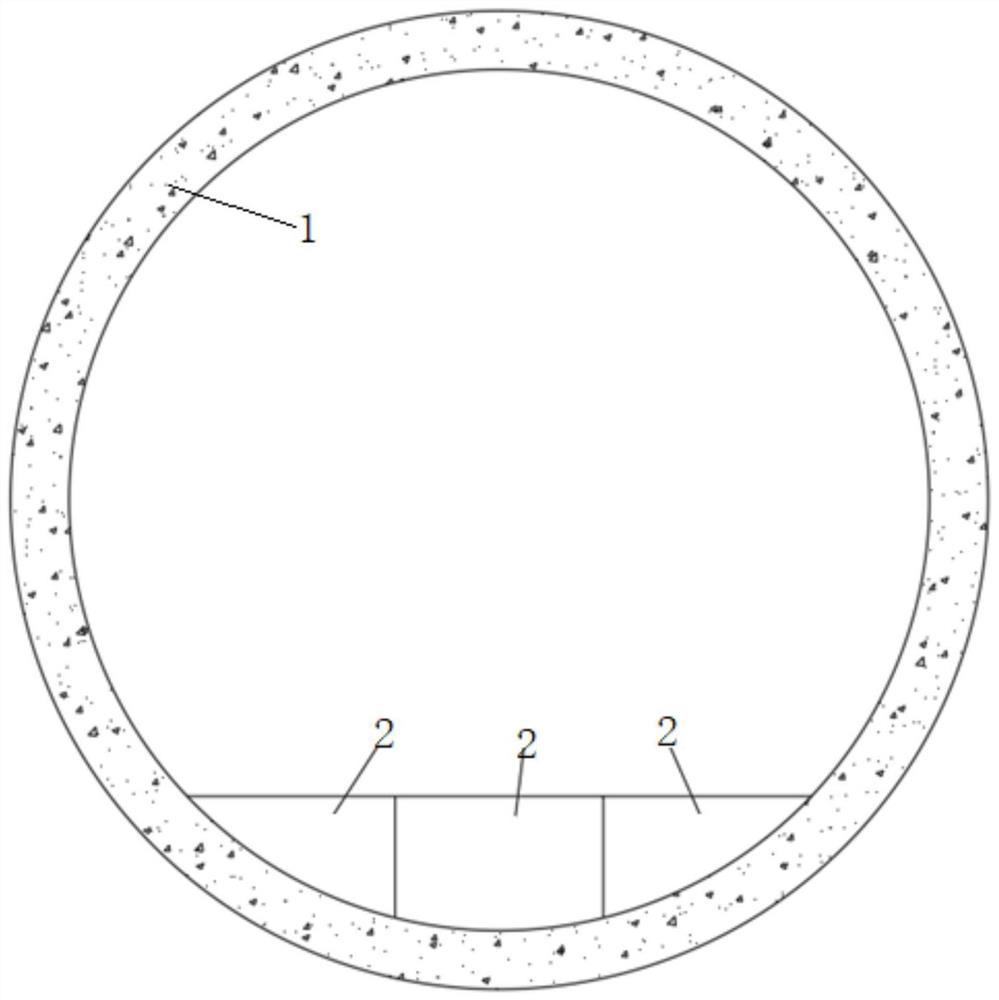
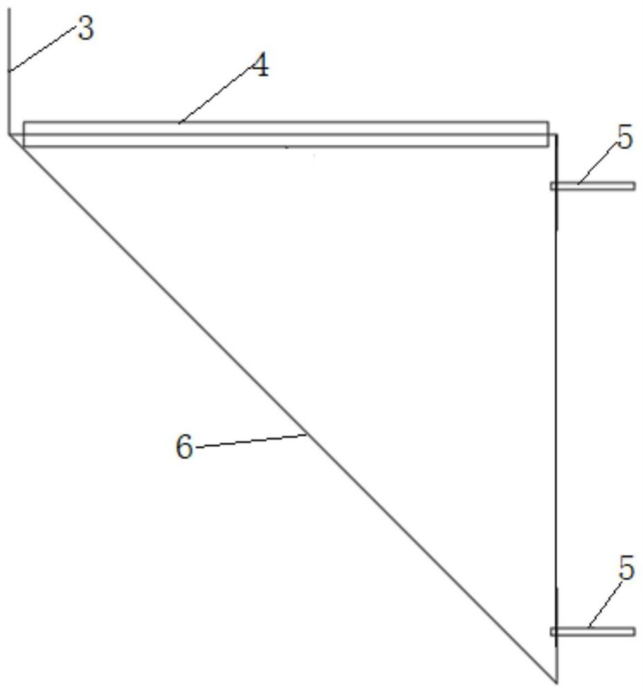
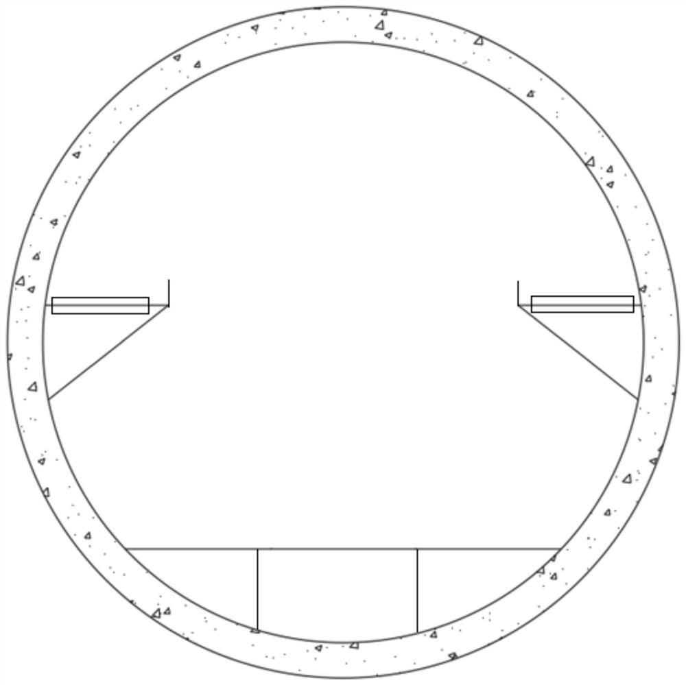
[0026] S1, such as figure 1 As shown, divide the concrete pad into several units and make prefabricated blocks 2, such as image 3 with Figure 4 As shown, the supporting roller 4 is installed along the line in the jacking pipe 1, the conveyor belt 7 is installed along the supporting roller 4 and the power device of the conveyor belt is installed in the originating shaft, and the prefabricated block 2 is transported along the line from the originating shaft to the jacking pipe 1 through the conveyor belt 7 After assembling the prefabricated block 2 into a concrete cushion, remove the support roller 4 and the conveyor belt 7 and transfer them to the next jacking pipe 1 to continue the construction of the concrete ...


PUM


Abstract

The invention discloses a method for laying a concrete cushion and a steel pipe in a jacking pipe. The method comprises the following steps that the concrete cushion is divided into a plurality of units and precast blocks are manufactured, a support roller is installed along the line in the jacking pipe, a conveyor belt is installed along the line of the support roller, the precast blocks are conveyed from a starting shaft along the line in the jacking pipe through the conveyor belt, pulleys are placed along the line of the concrete cushion, pulleys of front and rear pairs are sequentially connected in series through wire cables, the steel pipes are pulled forwards and welded backwards to be lengthened, a next-section steel pipe is welded to a previous-section steel pipe in the starting shaft and then enters the jacking pipe, the steel pipes are supported in a sliding mode through the pulleys in the advancing process, the jacking pipe and the steel pipes are constructed at the same time, the two ends of the jacking pipe and the two ends of the steel pipe are clamped together through U-shaped steel clamps to be temporarily fixed, then the pulley is taken out, and grouting is conducted between the steel pipe and the jacking pipe. According to the method, the concrete cushion is high in construction efficiency, damage to an outer anticorrosive coating of the steel pipe is reduced, the overall construction time is shortened, and repeated using may be achieved.

Description

technical field [0001] The invention belongs to the field of municipal construction, and in particular relates to a method for laying a concrete cushion and a steel pipe in a pipe jacking. Background technique [0002] Most of the jacking pipes in municipal engineering are drainage pipes, the inner diameter is generally less than 3m, and concrete cushions and steel pipes are generally laid inside. [0003] Cast-in-situ construction is often used when laying concrete cushions in pipe jacking, but construction in narrow and super-long (nearly 100m long) pipe jacking is time-consuming and labor-intensive, and the quality is difficult to guarantee, and the maintenance of concrete will affect the subsequent construction. Concreting by hand is even more inefficient when the pump is inaccessible. [0004] When laying steel pipes in the pipe jacking, two methods are generally adopted. One is that the steel pipes are directly jacked after welding in the originating shaft. This metho...

Claims


Application Information

Patent Timeline
Patent Type & Authority Applications(China)
IPC IPC(8): F16L1/036F16L1/06
CPCF16L1/036F16L1/06
Inventor 廖红玉姚家平鲁丙奎周亭
Owner WUHAN YIYE CONSTR ENG
Learn More