
Slip-casting lifting method for city tunnel passing through existing buildings

A grouting lifting and building technology, applied in construction, infrastructure engineering, soil protection and other directions, can solve existing buildings (structures) to achieve dynamic control without system method, pile end bearing capacity loss, weakened pile problems such as lateral constraints, to achieve the effects of high construction efficiency, reduced differential settlement, and inhibition of subsequent settlement

Inactive Publication Date: 2009-07-22
BEIJING JIAOTONG UNIV
View PDF0 Cites 46 Cited by
  • Summary
  • Abstract
  • Description
  • Claims
  • Application Information

AI Technical Summary

Problems solved by technology

Generally, pile foundation underpinning is required in the following situations: ① excavation passes through the vicinity of the pile foundation, which weakens the lateral restraint of the pile and reduces the bearing capacity of the pile; ② excavation passes through the pile itself, resulting in a significant increase in the bearing capacity of the pile Decrease or disappear; ③ Excavation passes through a place very close to the bottom of the pile, causing a serious loss of bearing capacity at the pile end
[0008] At present, the control methods for new urban tunnels passing through existing buildings (structures) mainly focus on the reinforcement of the ground and the reinforcement of existing buildings (structures), while the existing buildings (structures) There is no systematic method to realize dynamic control of buildings

Method used


Image

  • Slip-casting lifting method for city tunnel passing through existing buildings
  • Slip-casting lifting method for city tunnel passing through existing buildings
  • Slip-casting lifting method for city tunnel passing through existing buildings

Examples


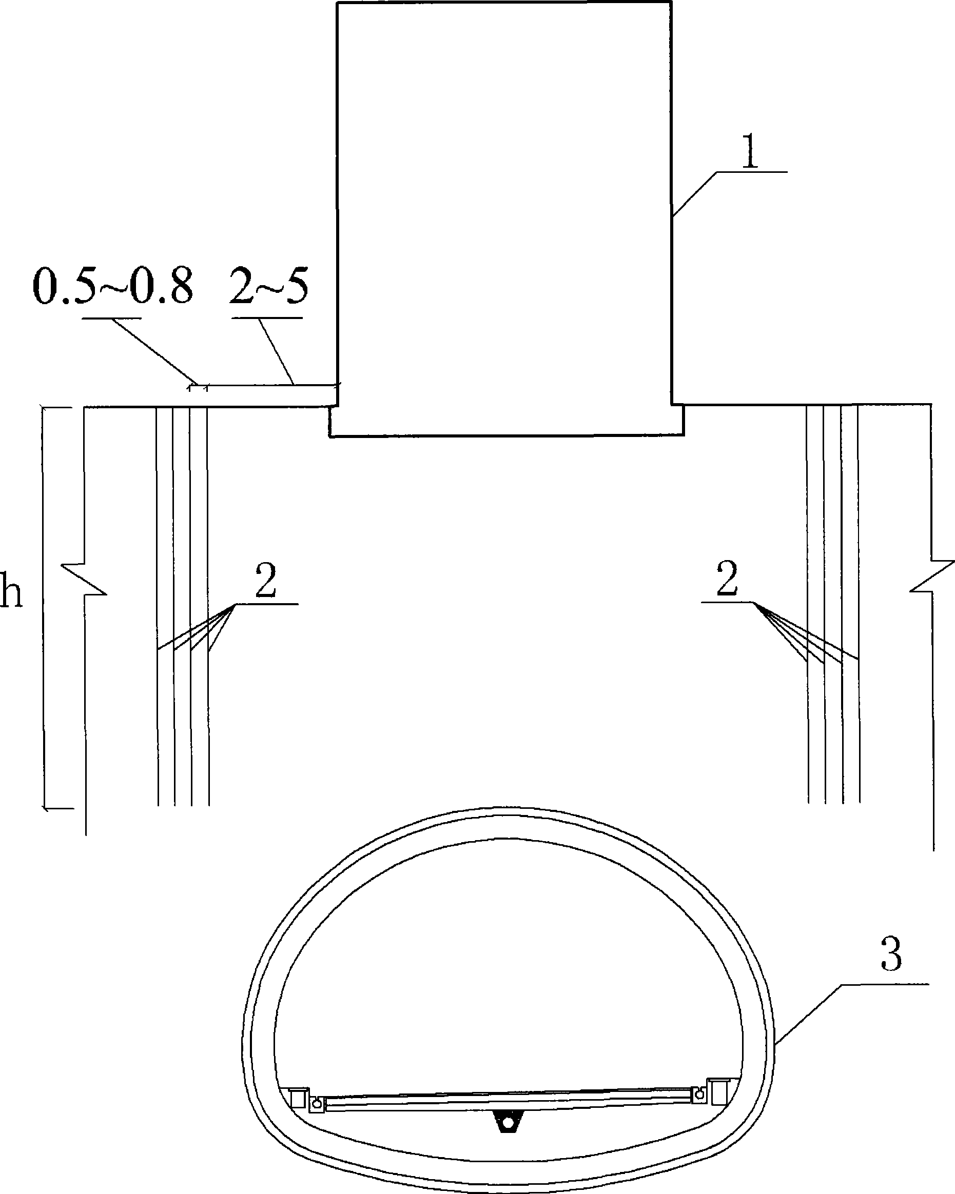
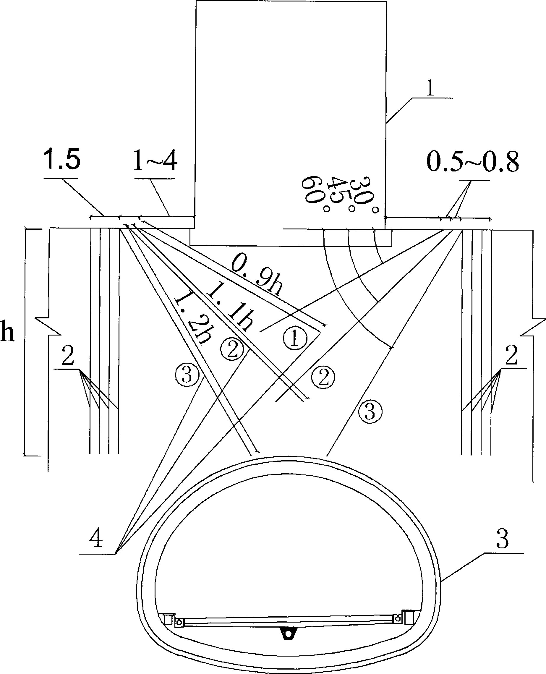
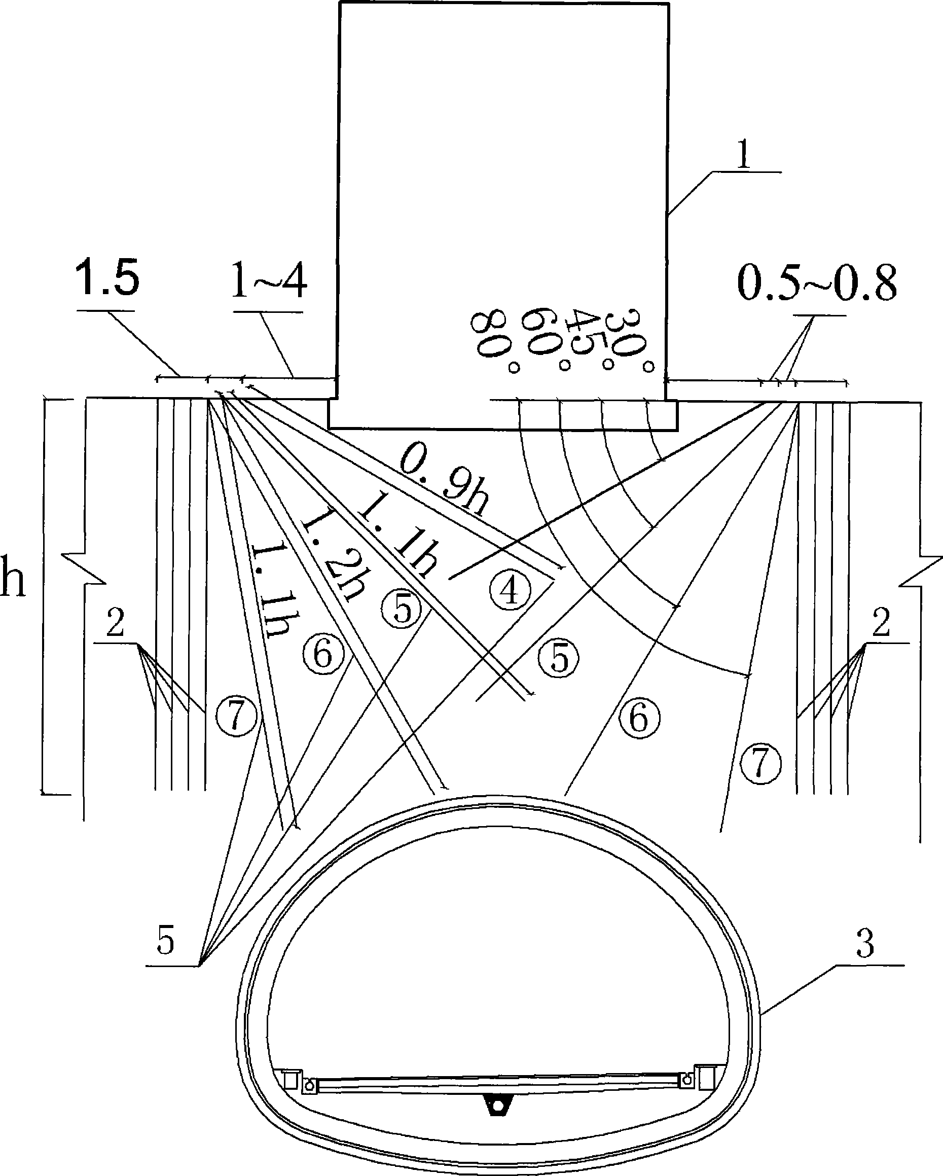
Embodiment Construction

[0027] The present invention will be described in detail below in conjunction with the accompanying drawings and specific embodiments.

[0028] This example adopts the technical scheme of the present invention to carry out construction, and provides detailed implementation and specific operation process, but the protection scope of the present invention is not limited to the following examples.

[0029] Take a residential building under a tunnel in a certain city as an example. The residential building was built in 1994 and is a brick-concrete residential building. The building has 7 floors and a total height of 20.1 meters. Its plane shape is rectangular, 56 meters long and 10.5 meters wide. The first floor is the storage room with a height of 2.1 meters, and the height of the other floors is 3.0 meters. The surrounding rock of this section of the tunnel is grade VI, with no self-stabilization ability. The soil at the top has a high water content and is prone to flow soil de...


PUM


Abstract

The invention discloses a method used for realizing the grouting during lifting when the city tunnel is threaded through the existing buildings, belonging to the underground tunnel construction technology field. The method includes the following steps: (1) the vertical grouting-stop bracing is carried out; (2) the foundation of the existing building is reconstructed and the foundation is grouted for reinforcement; (3) the dynamic tracking lift-grouting is carried out; (4) the lifting of a reconstructed building is resumed to guarantee that the settlement and differential settlement of the building are still in the controllable scope and simultaneously the grouting is stopped when the single max lifting reaches 2 to 3 mm. The invention has the effects that the grouting-stop maintaining operation can effectively restrict the lateral displacement of a soil body so as to enhance the lifting effect on the existing building by the following grouting; the grouting to the foundation for reinforcement can enhance the density of foundation and form a bearing stratum so as to lead the grouting lifting process to be smooth, effectively restrict the succeeding settlement of the existing building and also reduce the differential settlement.

Description

technical field [0001] The invention relates to a grouting lifting method for urban tunnels passing through existing buildings (structures), and belongs to the technical field of tunnel underground construction engineering. Background technique [0002] How to effectively control ground subsidence during tunnel excavation to protect the safety of buildings (structures) along the project is an important issue faced by urban underground engineering construction. In the city, the more densely populated the area with all kinds of buildings (structures), the more prominent the negative impact of tunnel construction will be. Regardless of whether it is an ordinary residential building or a building (structure) with other functions, once settlement, cracking or tilting occurs due to tunnel construction, it will not only affect the normal use of the building (structure), but also affect the normal work and life of the residents. It will bring a lot of inconvenience, and will also h...

Claims


Application Information

Patent Timeline
IPC IPC(8): E02D35/00E02D3/12
Inventor 张顶立张成平房倩侯艳娟骆建军苏洁
Owner BEIJING JIAOTONG UNIV
Learn More