
Graphite electrode end flattening device and method

A technology of graphite electrode and flat head, which is applied to grinding drive devices, machine tools suitable for grinding workpiece planes, grinding machines, etc. It can solve the problems of affecting normal work, large operating errors, and changes in the tightness of steel wire ropes, and achieves convenient length adjustments in time , The overall structure design is compact, and the effect of solving the inconvenience of processing

Pending Publication Date: 2021-07-23
SHANXI BEITERUI NEW ENERGY TECH
View PDF0 Cites 1 Cited by
  • Summary
  • Abstract
  • Description
  • Claims
  • Application Information

AI Technical Summary

Problems solved by technology

[0004] 1. The traditional equipment of manual operation and manual measurement is still used. It is inconvenient to adjust the distance between the grinding discs according to the length of the graphite electrode. Due to interference from human factors, there are problems of large operating errors and low measurement accuracy;
[0005] 2. When the graphite electrode has a flat head, place it on the trolley. First, it needs to be centered manually, that is, check whether it is in the middle of the grinding discs at both ends by manual means. It usually takes two or three times to achieve the centering, and then the trolley passes through the steel wire rope below. Traction movement for grinding, long time will also cause the wire rope to change in tension, or even break, affecting normal work

Method used


Image

  • Graphite electrode end flattening device and method
  • Graphite electrode end flattening device and method
  • Graphite electrode end flattening device and method

Examples


Embodiment 1

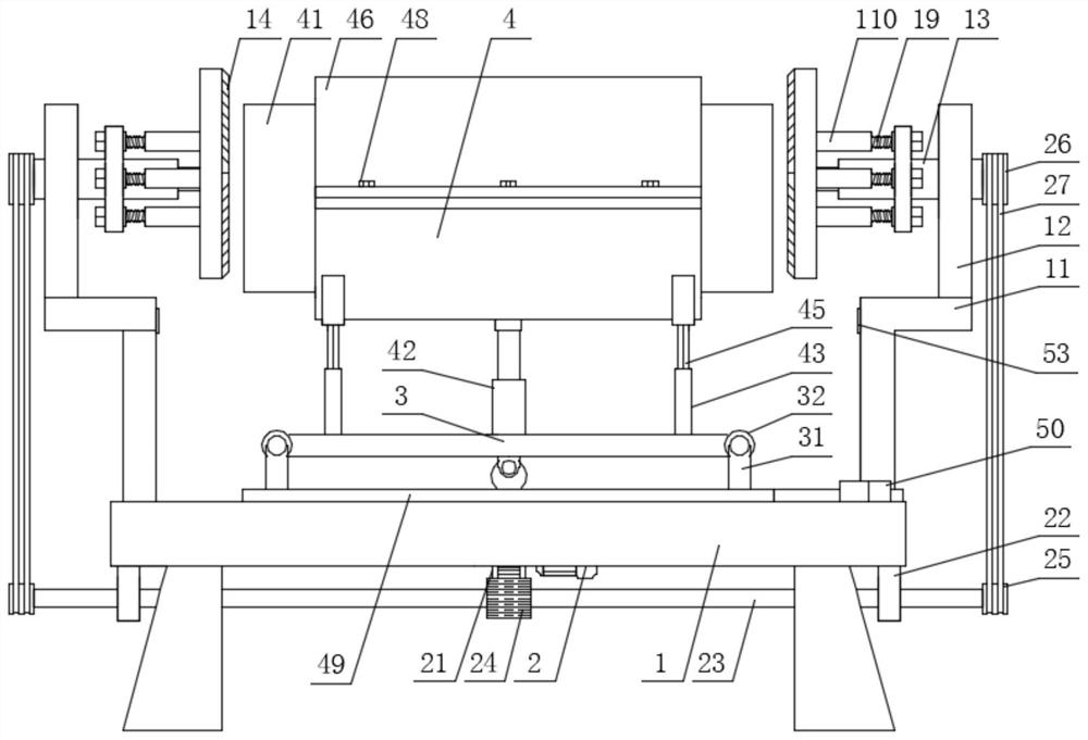
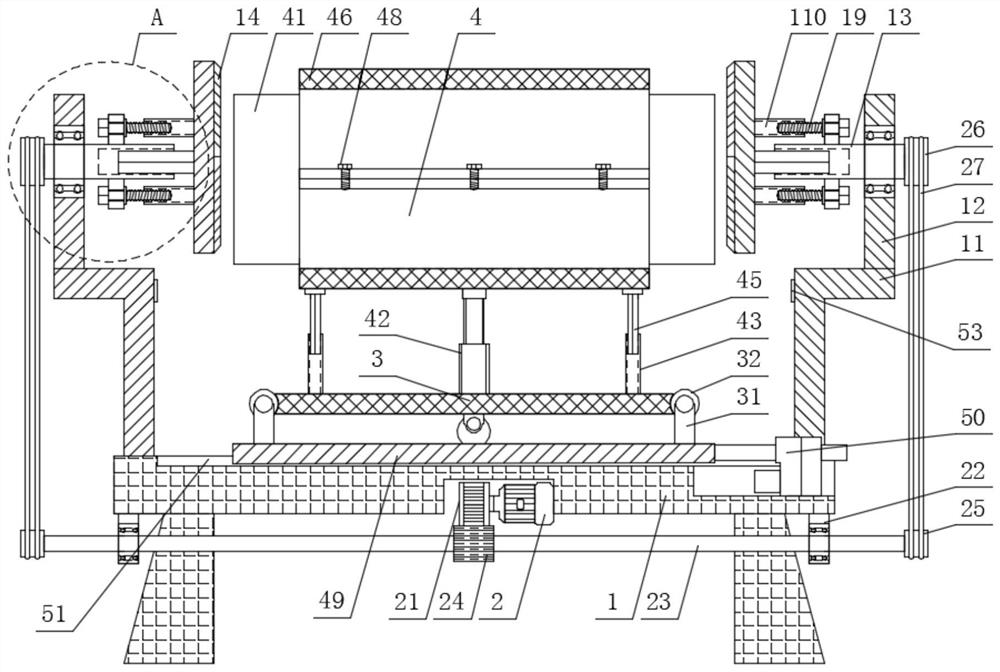
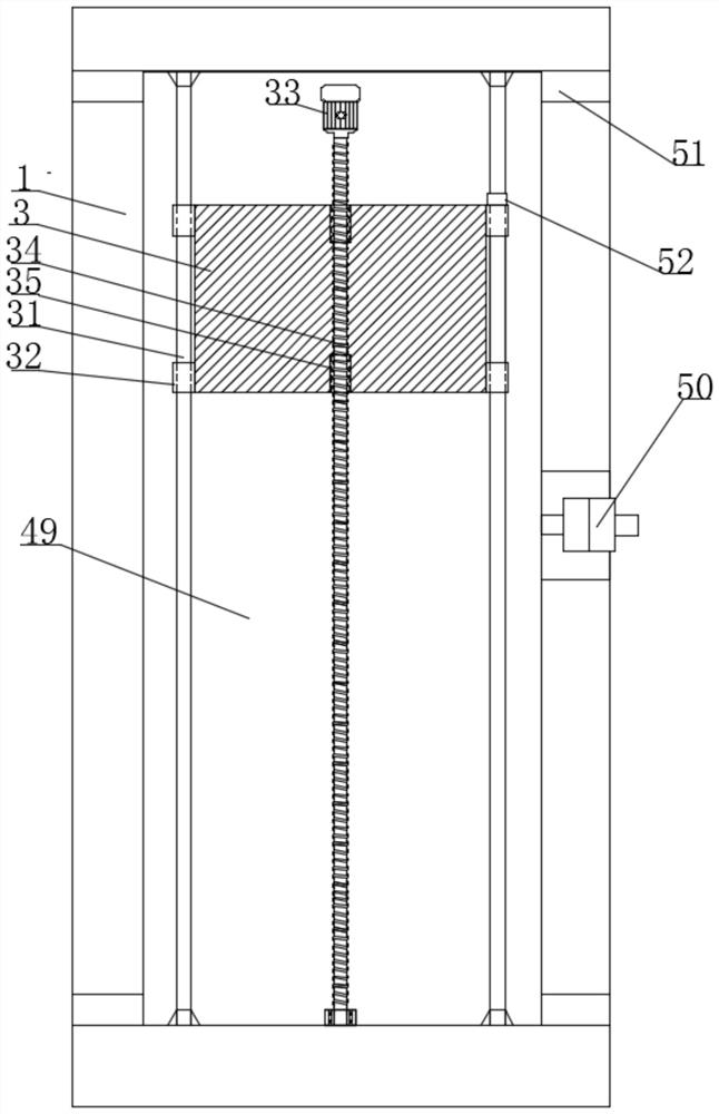
[0041] Embodiment 1: This embodiment provides a graphite electrode flat head device, see Figure 1-5 Specifically, it includes a base plate 1, a sliding mechanism, a lifting mechanism, and a driving mechanism. The base plate 1 is a rectangular plate placed horizontally and horizontally. The middle part of the top surface of the base plate 1 is provided with a horizontal plate 3 placed horizontally. The mechanism is connected with the bottom plate 1, and the top of the horizontal plate 3 is provided with a horizontally placed semicircular clamp 4, and the semicircular clamp 4 is provided with a horizontally placed graphite electrode 41, and the horizontal plate 3 is connected with the semicircular clamp 4 through a lifting mechanism;

[0042] Both sides of the top surface of the bottom plate 1 are provided with a pair of symmetrically fixed L-shaped plates 11, and the outer sides of the top surface of each L-shaped plate 11 are provided with vertically fixed side plates 12, and ...

Embodiment 2

[0051] Embodiment 2: In Embodiment 1, there is also the problem that the graphite electrode is not firmly fixed during processing. Therefore, on the basis of Embodiment 1, this embodiment also includes:

[0052] In the present invention, a movable hinged semicircle cover plate 46 is provided on the rear side of the top surface of the semicircle clamp 4, and a semicircle rubber pad 47 is provided on the inner wall of the semicircle cover plate 46 and the semicircle clamp 4, and two semicircle rubber pads are provided. The pads 47 are pressed against the upper and lower sides of the graphite electrode 41 respectively, and the front side of the semicircle cover plate 46 is evenly provided with some fastening bolts 48 that penetrate through the spiral. Side screw locking; center the graphite electrode 41 that needs to be polished flat on the semicircle clamping plate 4, cover the semicircle cover plate 46, and screw the fastening bolts 48 respectively, the inner ends of each fasten...

Embodiment 3

[0053] Embodiment three: see Image 6 , in the present embodiment, the present invention also proposes a method for using a graphite electrode flat head device, comprising the following steps:

[0054] Step 1, drive motor 2, sliding motor 33, linear motor 50, and hydraulic cylinder 42 are electrically connected to external power supply respectively through power line, according to the length of graphite electrode 41, adjust the distance between two flat-head grinding discs 14, through the rotating tool The word shaft 18 drives the screw rod 19 to cooperate with the threaded cylinder 110 to spirally rotate, and then drives the square rod 16 to slide outward or inward along the square groove 15, thereby changing the distance between the two flat-headed grinding discs 14;

[0055] Step 2, center the graphite electrode 41 that needs to be polished flat on the semicircle clamp 4, cover the semicircle cover 46, and screw the fastening bolts 48 respectively, the inner ends of each fa...


PUM


Abstract

The invention discloses a graphite electrode end flattening device which comprises a bottom plate, a sliding mechanism, a lifting mechanism and a driving mechanism. A transverse plate is arranged in the middle of the top face of the bottom plate, the bottom face of the transverse plate is connected with the bottom plate through the sliding mechanism, a semicircular clamping plate is arranged above the transverse plate, a graphite electrode is arranged in the semicircular clamping plate, and the transverse plate is connected with the semicircular clamping plate through the lifting mechanism. A pair of L-shaped plates are arranged on the two sides of the top face of the bottom plate, a side plate is arranged on the outer side of the top face of each L-shaped plate, a linkage bearing is arranged in the middle of each side plate, a linkage shaft is inserted in each linkage bearing, an end flattening grinding disc is arranged at the inner end of each linkage shaft, and the bottom face of the bottom plate is connected with the two linkage shafts through the driving mechanism. The invention further discloses a using method of the graphite electrode end flattening device. According to the graphite electrode end flattening device and the using method thereof, through the cooperative use of all the mechanisms, the overall structural design is compact, the position of the graphite electrode can be conveniently adjusted in multiple directions, and the graphite electrode end flattening machining efficiency is further improved.

Description

technical field [0001] The invention relates to the technical field of graphite electrode processing, in particular to a graphite electrode flat head device and method. Background technique [0002] Graphite electrode refers to petroleum coke, pitch coke as aggregate, coal tar pitch as binder, a kind of resistant electrode made by calcination of raw materials, crushing and grinding, batching, kneading, molding, roasting, impregnation, graphitization and mechanical processing. High temperature graphite conductive material. [0003] After the graphite electrode is formed, it also needs to be flushed to meet the specifications. The graphite electrode flat head equipment of the prior art has the following disadvantages: [0004] 1. The traditional equipment of manual operation and manual measurement is still used. It is inconvenient to adjust the distance between the grinding discs according to the length of the graphite electrode. Due to interference from human factors, there...

Claims


Application Information

Patent Timeline
Patent Type & Authority Applications(China)
IPC IPC(8): B24B7/17B24B7/22B24B41/04B24B47/12B24B47/20B24B47/22
CPCB24B7/17B24B7/22B24B41/04B24B47/12B24B47/20B24B47/22
Inventor 耿林华武建军龚军
Owner SHANXI BEITERUI NEW ENERGY TECH
Learn More