Equipment and process for preparing back passivation solar cell

A solar cell and back passivation technology, applied in the field of solar cells, can solve the problems of slow LPCVD coating rate, increased power consumption, high conductivity of amorphous/microcrystalline silicon film, and achieve film quality and passivation performance Excellent, reduce the ratio of high temperature deformation, save the effect of off-line doping equipment

Pending Publication Date: 2021-07-16
SUZHOU SHENGCHENG SOLAR EQUIP
View PDF7 Cites 2 Cited by
  • Summary
  • Abstract
  • Description
  • Claims
  • Application Information

AI Technical Summary

Problems solved by technology

[0002] The large-scale use of traditional fossil energy has caused serious damage to the environment, and is gradually facing the problem of exhaustion. Therefore, the use of new energy such as solar energy has become an important choice for human development. With the gradual realization of grid parity, the solar cell industry It has developed rapidly in recent years. At present, PERC solar cells occupy most of the solar cell market due to its high conversion efficiency and low manufacturing cost, but the improvement of its conversion efficiency has almost reached the bottleneck period, and the cost reduction space is relatively narrow. Considered to be the next generation solar cell technology route with higher conversion efficiency, Topcon solar cells can increase the conversion efficiency of industrialized solar cells by about 1-1.5%
[0003] At present, the equipment used to prepare tunneling silicon dioxide films and doped amorphous / microcrystalline silicon films for Topcon solar cells are generally low-pressure chemical vapor deposition coating LPCVD equipment (hereinafter referred to as LPCVD equipment), static plate plasma enhanced chemical Vapor deposition coating PECVD equipment (hereinafter referred to as PECVD equipment) or tubular PECVD coating equipment, the use of LPCVD equipment requires a very high process temperature, generally 500-900 ° C, which is easy to cause damage to the silicon wafer itself, and the high process temperature also increases equipment. Life loss, increased power consumption, and LPCVD coating rate is very slow, equipment production capacity is low, there are also very serious winding plating problems, and it is not easy to achieve online in-situ doping
[0004] Using static plate PECVD coating equipment to prepare the tunneling silicon dioxide layer and doped amorphous / microcrystalline silicon film layer of Topcon solar cells can improve the winding problem, increase the coating rate, and reduce the reaction temperature. The reaction temperature can be controlled within the range of 200-500°C, but it is difficult to control the uniformity of the film layer by using static plate PECVD equipment to prepare the ultra-thin silicon dioxide film layer, and the coating rate is fast, the film quality is not excellent enough, and The plasma coating process is accompanied by ion damage, which affects the passivation performance of silicon dioxide. When using static plate PECVD equipment to prepare doped amorphous / microcrystalline silicon thin films, due to the thick film layer, the film layer is 100-200nm , a larger coating chamber is required to increase production capacity, and the area of ​​the spray plate is also increased. When the temperature of the heating plate is higher than 250°C, the spray plate is prone to deformation after being radiated by the heating plate, which seriously affects the uniformity of the coating , and when the static plate PECVD equipment is used for coating, the plasma needs to be turned off when each tray enters and exits the coating chamber, and the chamber is pumped to the lowest pressure, and the tray needs a heating after entering the chamber The process of stabilizing and introducing the process gas to stabilize the pressure, and then turning on the plasma for coating, these actions waste the coating utilization time of the process chamber and reduce the production capacity
[0005] When using tubular PECVD equipment to prepare doped amorphous / microcrystalline silicon films, since the ceramic rods and ceramic collars connected between the graphite boats are easy to be plated with doped amorphous / microcrystalline silicon film layers, the doped The electrical conductivity of the final amorphous / microcrystalline silicon film layer is very high, which leads to the conduction between the positive and negative electrodes of the graphite boat, and the coating cannot be continued, so that the function of online doping cannot be realized. In addition, tubular PECVD equipment generally uses relatively low frequency Low power supply, generally 40KHz-250kHz, when coating with low frequency power supply, it is easy to produce heavy ion damage, which reduces the passivation effect of the film layer

Method used


Image

  • Equipment and process for preparing back passivation solar cell
  • Equipment and process for preparing back passivation solar cell

Examples


specific Embodiment 1

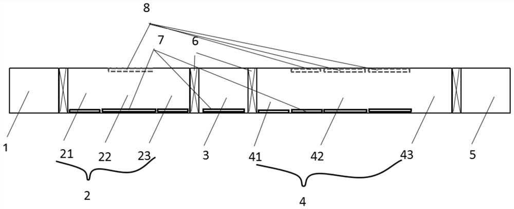
[0034] The tray is first introduced into the feeding chamber 11, and infrared lamps can be used to quickly heat the tray and silicon wafers, and then introduced into the first process chamber 2. The first process chamber 2 is composed of the first buffer chamber 21, the first coating chamber 22 and The second buffer chamber 23 is composed of three chambers, and the lower layer of the three chambers is covered with a heating plate 7, which can continuously heat the tray and silicon wafer. The tray enters the first buffer chamber 21 after being adjusted to the required process transmission speed. The first coating chamber 22, the first coating chamber 22 is provided with an upper electrode composed of a spray plate 8, the upper electrode is connected to a power supply, the frequency of the power supply is 40KHz-80MHz, and the spray plate 8 is provided with a plurality of uniformly distributed dense Exhaust holes, the process gas is evenly passed into the first coating chamber 22 ...

specific Embodiment 2

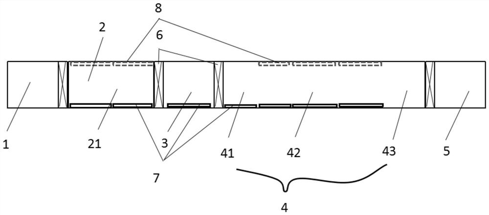
[0040] The structure and process flow of the first process chamber 2 in this embodiment are different from those in Embodiment 1, and the rest of the structure and process flow are consistent with Embodiment 1. The first process chamber 2 consists of n (n≥1) ALD or PEALD coating chambers Composed of 21 bodies, the lower side of the process chamber is covered with heating plates, the upper side of the coating chamber 21 is equipped with a gas spray plate or a plurality of pipeline inlets are arranged to replace the spray plate, and a vacuum pump is arranged in the cavity of the coating chamber 21 There are n trays (n n≥1) that can be placed on the air inlet and the lower heating plate. This process chamber is used to prepare an ultra-thin silicon dioxide film on the surface of the silicon wafer by atomic layer deposition (ALD). The material chamber 1 is then transferred to the first process chamber 2. After the first process chamber 2 is covered with pallets, the valves 6 on bot...

specific Embodiment 3

[0046] The process flow of the first process chamber 2 in this embodiment is different from that in Embodiment 1. The structure of the first process chamber 2 is consistent with that of the first process chamber in Embodiment 1, while the isolation chamber 3 and the second process chamber 4 are The structure and process flow are the same as those in Embodiment 1. The air extraction port is arranged on the lower side of the heating plate 7. There is a spray plate 8 on the upper side of the first coating chamber 22. Ozone is evenly introduced into the cavity through the pores of the spray plate 8, and the silicon The surface of the sheet is oxidized to silicon oxide, and the upper side of the first coating chamber 22 can also use a UV lamp to dissociate oxygen to form ozone. The formation of ozone can use an ozone generator or UV lamp to dissociate, etc., including but not limited to the above methods.

[0047] The first process chamber 2 can also adopt the method of static coati...


PUM

PropertyMeasurementUnit
thicknessaaaaaaaaaa

Abstract

The invention discloses equipment and a process for preparing a back passivation solar cell. The equipment and the process for preparing the back passivation solar cell comprise a feeding cavity, a first process cavity, an isolation cavity, a second process cavity and a discharging cavity, valves are arranged among cavity bodies of the feeding cavity, the first process cavity, the isolation cavity, the second process cavity and the discharging cavity; heating plates are laid in the first process cavity and the second process cavity, a transmission roller is arranged in each cavity which is connected in sequence, a tray loaded with a silicon wafer is transmitted on the rollers, and the tray loaded with the silicon wafer passes through the feeding cavity, the first process cavity, the isolation cavity, the second process cavity and the discharging cavity in sequence. Through the mode, a tunneling silicon dioxide film layer and a doped amorphous/microcrystalline silicon film layer of the Topcon solar cell are prepared at the same time, the Topcon solar cell with higher efficiency can be prepared, ion damage is avoided, dynamic transmission is achieved, the uniformity of the film layers is improved, and the productivity is improved.

Description

technical field [0001] The invention relates to the technical field of solar cells, in particular to a device for preparing a back passivated solar cell and a process thereof. Background technique [0002] The large-scale use of traditional fossil energy has caused serious damage to the environment, and is gradually facing the problem of exhaustion. Therefore, the use of new energy such as solar energy has become an important choice for human development. With the gradual realization of grid parity, the solar cell industry It has developed rapidly in recent years. At present, PERC solar cells occupy most of the solar cell market due to its high conversion efficiency and low manufacturing cost, but the improvement of its conversion efficiency has almost reached the bottleneck period, and the cost reduction space is relatively narrow. Considered to be the next-generation solar cell technology route with higher conversion efficiency, Topcon solar cells can increase the conversi...

Claims


Application Information

Patent Timeline
Patent Type & Authority Applications(China)
IPC IPC(8): C23C16/50C23C16/24C23C16/455C23C16/54H01L31/0216
CPCC23C16/50C23C16/24C23C16/54C23C16/45544C23C16/45565H01L31/02167Y02E10/50
Inventor 李长江周文彬杨星
Owner SUZHOU SHENGCHENG SOLAR EQUIP
Why Eureka
Try Eureka