
Assembling process of double oil cylinder pushing mechanism for injection molding machine

A technology of moving mechanism and assembly process, which is applied in the field of oil cylinder assembly process, can solve the problems of low efficiency and long time of pushing the oil cylinder, etc., and achieve the effect of reducing length, improving performance and reducing volume

Active Publication Date: 2022-06-28
余姚市鹰图机械设备有限公司
View PDF0 Cites 0 Cited by
  • Summary
  • Abstract
  • Description
  • Claims
  • Application Information

AI Technical Summary

Problems solved by technology

When closing the mold, mechanical power or hydraulic power is used. The hydraulic power is to use the hydraulic rod to push the piston rod to move to push the cylinder to close the mold. However, the structure in the prior art makes the hydraulic oil push the cylinder for a long time and has low efficiency.

Method used


Image

  • Assembling process of double oil cylinder pushing mechanism for injection molding machine
  • Assembling process of double oil cylinder pushing mechanism for injection molding machine
  • Assembling process of double oil cylinder pushing mechanism for injection molding machine

Examples


Embodiment 1

[0039] The abrasive described in this example is made from the following raw materials by weight: 53 parts of diamond micropowder, 32 parts of corundum micropowder, 29 parts of triethanolamine, 50 parts of glycerin, 14 parts of polyacrylamide, 20 parts of polypropylene glycol, calcium hydrogen phosphate 7 parts, 5 parts of sodium silicate, 25 parts of talcum powder, the particle size of corundum micro-powder is 70um, and the particle size of corundum micro-powder is 180um.

[0040] Add acetic acid pH regulator to the diamond micropowder to make the diamond powder aqueous solution at a pH of 6.5-8.5, and then classify and purify to obtain the diamond micropowder;

[0041] When the relative air humidity is greater than 85%, dry the diamond micropowder, weigh 53 g of pure diamond micropowder, add 32 parts of corundum micropowder, 14 parts of polyacrylamide, 20 parts of polypropylene glycol, 7 parts of calcium hydrogen phosphate, 5 parts of sodium silicate, 25 parts of talcum powd...

Embodiment 2

[0043] The abrasive described in this example is made from the following raw materials by weight: 54 parts of diamond micropowder, 38 parts of corundum micropowder, 28 parts of triethanolamine, 12 parts of polyacrylamide, 19 parts of polypropylene glycol, 6 parts of calcium hydrogen phosphate, silicon dioxide 4 parts of sodium; the particle size of diamond micro-powder is 61um, the particle size of corundum micro-powder is 152um, 60 parts of glycerin, and 30 parts of talc.

[0044] Add acetic acid pH regulator to the diamond micropowder to make the diamond powder aqueous solution at a pH of 6.5-8.5, and then classify and purify to obtain the diamond micropowder;

[0045] When the relative air humidity is greater than 85%, the diamond micropowder is dried, and 53 g of pure diamond micropowder is weighed, and 38 parts of corundum micropowder, 12 parts of polyacrylamide, 19 parts of polypropylene glycol, 6 parts of calcium hydrogen phosphate, and 4 parts of sodium silicate are add...


PUM


Abstract

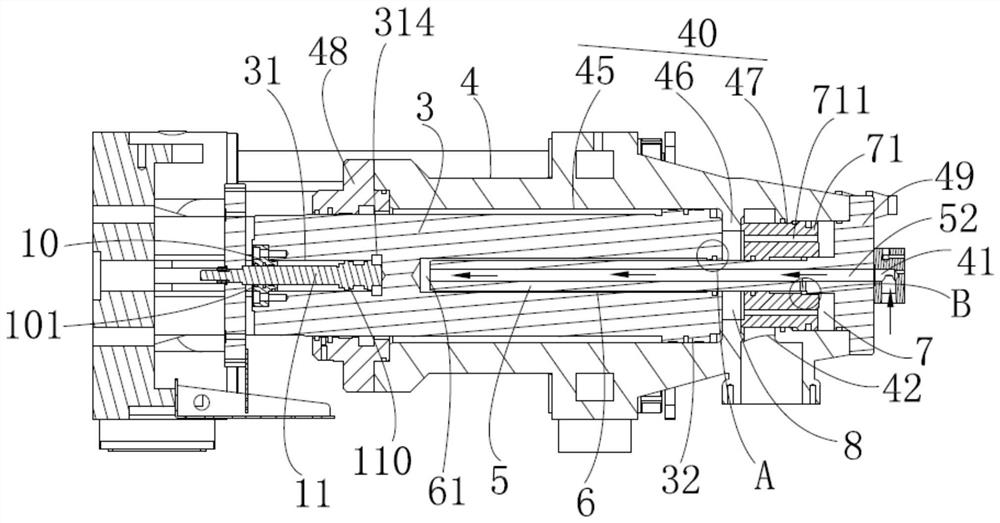
The assembly process of the double oil cylinder pushing mechanism for injection molding machine disclosed in the present invention, S1, inserting the first plunger into the first flow cavity in the cylinder body; S2, contacting the side wall of the annular protrusion on the second piston One end surface is coated with abrasive, and then the second piston coated with abrasive is placed into the second flow chamber through the second flow chamber port in the cylinder; S3, the side with abrasive on the second piston and The side wall of the annular protrusion is in close contact with and rotates after applying pressure to the second piston at the same time. The side wall of the annular protrusion and the side with abrasive on the second piston are ground mutually so that the side wall of the annular protrusion and the second piston Sealing is achieved between one side of the piston; S4. Use the third end cover and the sealing ring to close the port of the second flow chamber, and insert the pressurized plunger on the third end cover through the perforation of the second piston In the pressurized chamber at the end of the first plunger. It improves the driving efficiency, and the end surface of the piston has a high tightness with the surface in contact with it.

Description

technical field [0001] The invention relates to the technical field of an oil cylinder assembly process, in particular to an assembly process of a double oil cylinder pushing mechanism for an injection molding machine. Background technique [0002] The function of the clamping system on the injection molding machine is to ensure that the molding mold can be opened and closed flexibly, accurately, quickly, reliably and safely, to ensure that the mold cavity is tightly closed and the plastic melt will not overflow outside the cavity. When clamping the mold, mechanical power or hydraulic power is used. When using hydraulic power, the hydraulic rod is used to push the piston rod to move to push the cylinder to close the mold. However, the structure in the prior art makes the hydraulic oil push the cylinder for a long time and has low efficiency. SUMMARY OF THE INVENTION [0003] The purpose of the present invention is to design an assembly process of a double-cylinder pushing ...

Claims


Application Information

Patent Timeline
Patent Type & Authority Patents(China)
IPC IPC(8): B29C45/67
CPCB29C45/67
Inventor 唐亮亮
Owner 余姚市鹰图机械设备有限公司
Learn More