Fuzzy self-tuning pid control algorithm for interleaved parallel bidirectional dc/dc converter
A control algorithm, a technology of fuzzy controller, applied in control/regulation system, conversion of DC power input to DC power output, instruments, etc., can solve the problems that the control effect is difficult to achieve expectations, the fuzzy rules and proportional coefficient correction are complicated, etc. Improve static performance, fast dynamic response, and improve the effect of dynamic performance
- Summary
- Abstract
- Description
- Claims
- Application Information
AI Technical Summary
Problems solved by technology
Method used
Image
Examples
specific Embodiment approach 1
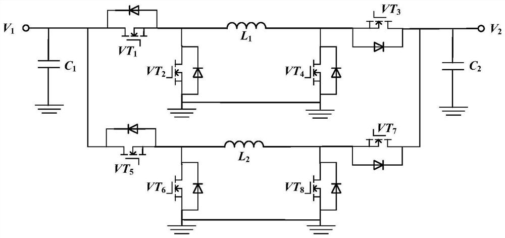
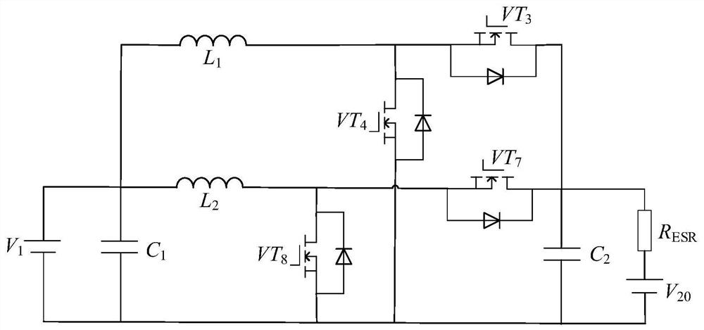
[0073] Specific implementation mode one: the following combination figure 1 and figure 2 Explain the establishment process of the small-signal model of the interleaved parallel bidirectional DC / DC converter. The bidirectional DC / DC converter is obtained by parallel connection of two sets of synchronous four-switch Buck-Boost converters. According to the different directions of energy flow on both sides of the converter, the converter Can work in Buck mode and Boost mode respectively.
[0074] (1) When the bidirectional DC / DC converter works in the interleaved parallel Boost state, VT 1 and VT 5 stay on, VT 2 and VT 6 remains off, VT 3 and VT 7 Working with a certain duty cycle, VT 4 and VT 8 Working with a complementary duty cycle with dead time, the state-space average equation of the inductor voltage and capacitor current is obtained according to the small-signal modeling method of the DC-DC converter as:
[0075]
[0076]
[0077]
[0078] Among them, V ...
specific Embodiment approach 2
[0086] Specific implementation mode two: Calculate the transfer function G according to the equivalent circuit of the small signal model id (s), G vd (s), G vi (s).
[0087] (3) In forward Boost mode, the input side V 1 Equivalent to the charging side, the disturbance amount on the input side Laplace transform the state-space average equations (1) to (3) of the inductor voltage and capacitor current in the forward boost charging mode, and combine the equation (4) to obtain the duty cycle and the transfer of the inductor current functionG id (s), duty cycle and voltage V 2 The transfer function G vd (s) and inductor current versus voltage V 2 The transfer function G vi (s) are:
[0088]
[0089]
[0090]
[0091] (4) In reverse Buck mode, the input side V 2 Equivalent to the charging side, the disturbance amount on the input side Laplace transform the state space average equations (5) to (7) of the inductor voltage and capacitor current in the reverse Buck...
specific Embodiment approach 3
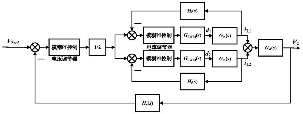
[0095] Specific implementation mode three: the following combination image 3 and Figure 4 Describe the working principle of the forward Boost mode control system block diagram. The basic control strategy is a double closed-loop control of the voltage outer loop and the current inner loop. The inner loop has two identical branches, each of which has a current loop; the set voltage reference value V ref and the actual output voltage collected by V 2 Compare to get the voltage error V e , the input voltage loop fuzzy PI controller, the PI controller will output the total inductor current reference value I Lref ;Set the total current reference value I Lref After equalization, it is used as the inductor current reference value of the two current inner loops, and the collected inductor current I L1 , I L2 Compare to get the inductor current error I Le1 , I Le2 , input each current loop fuzzy PI controller, and the current loop fuzzy PI controller outputs the driving pulse ...
PUM
 Abstract
Description
Claims
Application Information
 - R&D
- Intellectual Property
- Life Sciences
- Materials
- Tech Scout
- Unparalleled Data Quality
- Higher Quality Content
- 60% Fewer Hallucinations
Browse by: Latest US Patents, China's latest patents, Technical Efficacy Thesaurus, Application Domain, Technology Topic, Popular Technical Reports.
© 2025 PatSnap. All rights reserved.Legal|Privacy policy|Modern Slavery Act Transparency Statement|Sitemap|About US| Contact US: help@patsnap.com


