
Stripping and grinding machine for separating iron particles and silicate minerals from steel slag, and using method thereof

A technology of silicate minerals and iron particles, which is applied in the field of metallurgy, can solve the problems that steel slag tailings cannot be utilized as resources, steel slag cannot be processed in place, land occupation and environmental protection pressure are high, and the structure is simple, installation and layout are simple, The effect of high work efficiency

Active Publication Date: 2021-06-22
XI'AN UNIVERSITY OF ARCHITECTURE AND TECHNOLOGY
View PDF18 Cites 0 Cited by
  • Summary
  • Abstract
  • Description
  • Claims
  • Application Information

AI Technical Summary

Problems solved by technology

Traditional material crushing equipment processes steel slag, constantly breaking and grinding, energy consumption and material wear are serious, and steel slag cannot be processed in place. The final steel slag tailings are part of the iron particles wrapped by silicate phase minerals, that is, the active mineral silicon in steel slag. Iron-rich materials such as salt phase and some iron particles cannot be further separated. Due to this limitation, large-scale resource utilization of steel slag tailings cannot be realized. Steel slag tailings in all iron and steel enterprises are piled up like mountains, which occupies a huge area and pressures on environmental protection

Method used


Image

  • Stripping and grinding machine for separating iron particles and silicate minerals from steel slag, and using method thereof
  • Stripping and grinding machine for separating iron particles and silicate minerals from steel slag, and using method thereof
  • Stripping and grinding machine for separating iron particles and silicate minerals from steel slag, and using method thereof

Examples


Embodiment Construction

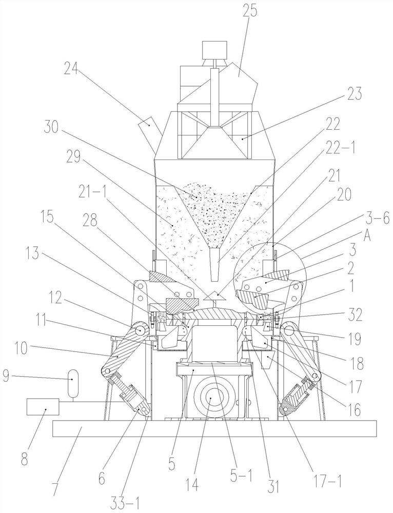
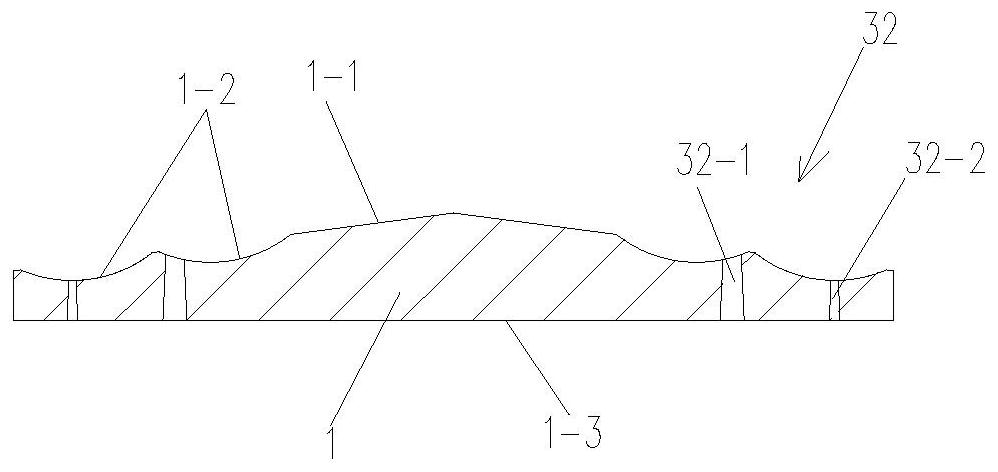
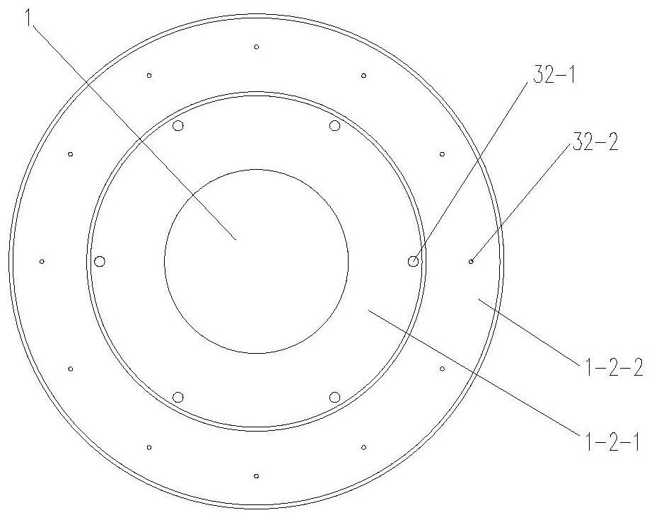
[0095] Such as Figure 1 to 17 The peeling machine separated from ferrite and silicate mineral in a steel slag, including a base 7, a housing 20, a horizontal rotation mounting, a lower rotating resistant body 1 and a lower rotating mill 1 The upper fixing grinding body 2, the lower rotating mill 1 and the upper fixing grinding body 2 form a peeled abrasive chamber 28, and the base 7 is provided with a pressure of steel slag 30 in the peeling chamber 28. Stripping pressure mechanism, the pressing mechanism drives the upper fixing grinding body 2 to be close or away from the lower rotary barrier 1;

[0096] The top of the housing 20 is provided with a feed tube 24 and a mount powder, and a lower body strip 22 is provided in the top of the housing 20, and the bottom and the housing of the mutter powder plate 23. 20 Inner communication, between the top of the lower hopper 22 and the bottom of the cage pickup machine 23 are provided with a gap, and a gap is provided between the top edg...


PUM

PropertyMeasurementUnit
diameteraaaaaaaaaa

Abstract

The invention discloses a stripping and grinding machine for separating iron particles and silicate minerals from steel slag, and a using method thereof. The stripping and grinding machine comprises a base, a shell, a lower rotary grinding body and an upper fixed grinding body, wherein a stripping and grinding cavity is formed between the lower rotary grinding body and the upper fixed grinding body, and a pressing mechanism is arranged on the base; the upper fixed grinding body is driven by the pressing mechanism to get close to or keep away from the lower rotary grinding body, and a feeding pipe and a rotating cage powder concentrator are arranged on the top of the shell; and a separation channel for stripped and ground iron particles and silicate mineral powder to pass and separate is formed in the lower rotary grinding body. The method comprises the following step I of preparation before use; the step II of stripping and grinding of the steel slag; the step III of separation of the iron particles and silicate minerals. The stripping and grinding machine is reasonable in design, stripping and grinding separation of the iron particles and silicate minerals from the steel slag is achieved, the large-scale resource utilization is achieved, and large-scale solid waste utilization of the steel slag is met.

Description

Technical field [0001] The present invention belongs to a comminuted and separation apparatus in the field of metallurgical technology, and more particularly to a peeling machine separated from ferrous and silicate mineral in steel slag and its use. Background technique [0002] As we all know, when the steel smelting steel slag is currently treated in the metallurgical industry, the general use of material crushing equipment is mainly a crusher. After multi-segment breaking iron, it is finally less than 10 mm steel slag, of which the total iron content is from 17% to 22%. In the room, the moniral iron content is 2% to 3%, and the remaining in the form of ferrous metal oxide solids RO, MgO is present. Traditional material crushing equipment Treat steel slag, continuous break, grinding, energy consumption and material wear, can not treat steel slag in place, last formed steel slag tailings, due to partial iron grains, mineral silicon The iron-rich materials such as acid salts and ...

Claims


Application Information

Patent Timeline
Patent Type & Authority Applications(China)
IPC IPC(8): B02C7/08B02C7/11B02C7/16B02C23/12B02C23/20C21B3/06
CPCB02C7/08B02C7/11B02C7/16B02C23/12B02C23/20C21B3/06C21B2400/02C21B2400/052Y02W30/50
Inventor 程福安刘宁昌陈延信李琦
Owner XI'AN UNIVERSITY OF ARCHITECTURE AND TECHNOLOGY
Learn More