Corrugated paperboard cutting device

A cutting device and a technology for corrugated cardboard, applied in the field of corrugated cardboard, can solve the problems of changes in the shape and protective ability of the corrugated paper cutting opening, inconvenient for workers to clean work, unfavorable protective work, etc., so as to improve cutting efficiency, ensure protective performance, and avoid deformation. Effect

Pending Publication Date: 2021-06-11
王佳琪
View PDF1 Cites 0 Cited by
  • Summary
  • Abstract
  • Description
  • Claims
  • Application Information

AI Technical Summary

Problems solved by technology

[0006] Aiming at the deficiencies of the prior art, the present invention provides a corrugated cardboard cutting device, which solves the problem that current corrugated cardboard cutting equipment adopts extrusion blades to realize cutting, and the extrusion force at the corrugated cardboard cutting mouth will undergo irreversible deformation, so that the corrugated cardboard is cut The shape and protection ability of the mouth change, which is not conducive to the protection work after cutting. At the same time, the traditional cutting equipment accumulates a lot of dust after long-term use, which is not convenient for workers to clean.

Method used


Image

  • Corrugated paperboard cutting device
  • Corrugated paperboard cutting device
  • Corrugated paperboard cutting device

Examples


Embodiment 1

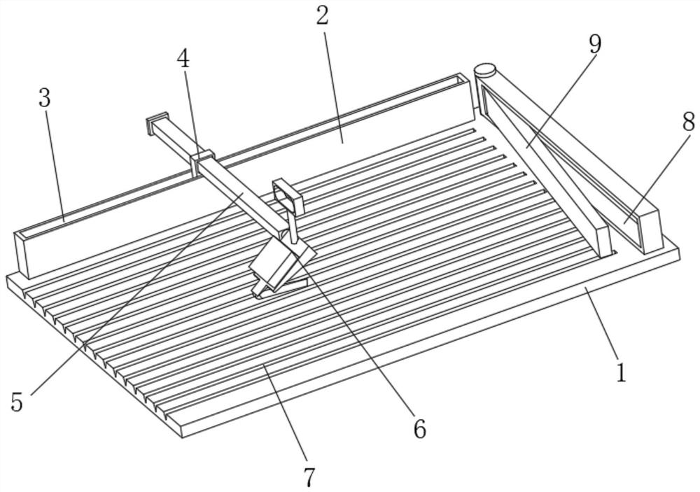
[0032] Such as figure 1 As shown, the present invention provides a technical solution: a corrugated cardboard cutting device, including a support pad 1, the back side of the top of the support pad 1 is fixedly connected with a limiting straight plate 2, and the top of the limiting straight plate 2 is provided with a limit track 3. The inside of the bit track 3 is slidably connected with an adjustment block 4, and the inside of the adjustment block 4 runs through and is slidably connected with a support insert rod 5. The end of the support insert rod 5 located at the front of the adjustment block 4 is rotatably connected with a cutting mechanism 6, and the support pad The surface of the top of the board 1 is uniformly and equidistantly provided with limiting grooves 7, the bottom of the cutting mechanism 6 is set correspondingly to the limiting grooves 7, the right side of the top of the supporting pad 1 is fixedly connected with a right-angled support plate 8, and the limiting ...

Embodiment 2

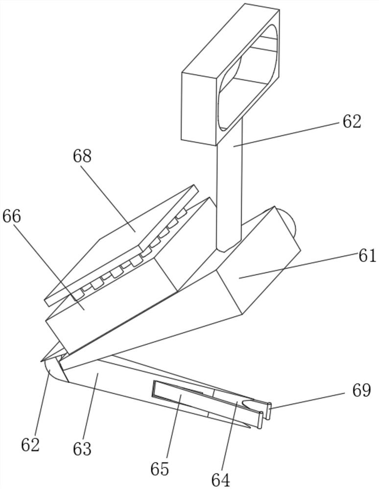
[0034] Such as Figure 2-4 As shown, on the basis of Embodiment 1, the present invention provides a technical solution: a corrugated cardboard cutting device, the cutting mechanism 6 includes an adjustment slant plate 61, and the position on the back of the adjustment slant plate 61 and near the upper side and the support insertion rod 5 Rotation connection, the top of the adjustment slant plate 61 is fixedly connected with a handle bar 62, the bottom end of the adjustment slant plate 61 is fixedly connected with a protective arc block 62 near the left side, and the bottom end of the adjustment slant plate 61 is located at the bottom of the protective arc block 62. The right side is fixedly connected with an extension guide rod 63 .

[0035] A blade assembly 64 is fixedly connected to the right end surface of the extension guide rod 63 , and a guide insertion rod 65 is rotatably connected to the front and rear sides of the extension guide rod 63 and near the right side. Reali...

Embodiment 3

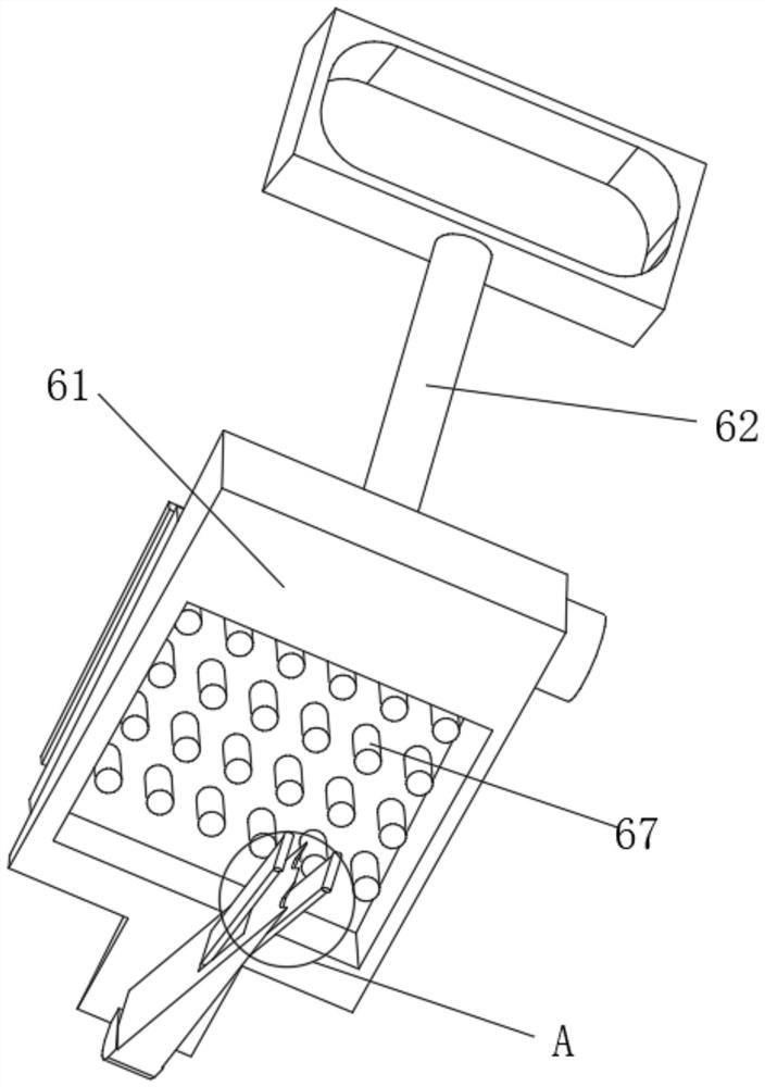
[0040] Such as Figure 5 As shown, on the basis of Embodiment 1 and Embodiment 2, the present invention provides a technical solution: a corrugated cardboard cutting device, the cleaning assembly 67 includes a support insert 671, and the support insert 671 is located at one end above the storage slot 66 It is fixedly connected with the processing pull plate 68 , and one end of the support insert 671 located inside the storage groove 66 is evenly and fixedly connected with a cleaning brush rod 672 .

[0041] The outer surface of the cleaning brush rod 672 is uniformly and fixedly connected with a scraper cone 673 , and the outer surface of the scraper cone 673 is evenly provided with an adsorption groove 674 . Increase the dust absorption capacity and improve the ability to clean the adsorbed dust.

[0042] Working principle: Attach the right-angled side of the corrugated cardboard to the surface of the limiting straight board 2, adjust the angle of the bevel adjustment plate ...


PUM


Abstract

The invention discloses a corrugated paperboard cutting device which comprises a supporting base plate. A limiting straight plate is fixedly connected to the reverse side of the top of the supporting base plate, a limiting rail is arranged on the top of the limiting straight plate, an adjusting sleeve block is connected with the interior of the limiting rail in a sliding mode, and a supporting insertion rod penetrates through the adjusting sleeve block and is connected with the interior of the adjusting sleeve block in a sliding mode. A cutting mechanism is rotationally connected with the end, located on the obverse side of the adjusting sleeve block, of the supporting insertion rod, limiting grooves are evenly formed in the surface of the top of the supporting base plate at equal intervals, the bottom of the cutting mechanism is arranged in the mode of corresponding to the limiting grooves, a right-angle supporting plate is fixedly connected to the right side of the top of the supporting base plate, the limiting rail is perpendicular to the right-angle supporting plate, and the middle of the end face of the left side of the right-angle supporting plate is rotationally connected with an oblique angle adjusting plate. The invention relates to the technical field of corrugated paperboards. According to the corrugated paperboard cutting device, fixing of non-rectangular corrugated paper is achieved, and the situation that a wavy paper element and the limiting grooves are kept parallel is guaranteed.

Description

technical field [0001] The invention relates to the technical field of corrugated cardboard, in particular to a corrugated cardboard cutting device. Background technique [0002] Corrugated cardboard is also called corrugated cardboard. It is made of at least one layer of corrugated paper and one layer of cardboard paper, which has good elasticity and extensibility. It is mainly used in the manufacture of cartons, the sandwich of cartons and other packaging materials for fragile goods. It mainly adopts domestic straw pulp and waste paper to be beaten to make raw cardboard similar to yellow cardboard, and then it is machined and rolled into a corrugated shape, and then the surface is bonded with boxboard paper with an adhesive such as sodium silicate. [0003] For example, the Chinese invention publication number is: a cutting device for corrugated paper of CN105108783B, comprising a frame, a cutting plate is arranged under the frame, a cutting device is arranged on the fra...

Claims


Application Information

Patent Timeline
IPC IPC(8): B26D1/08B26D5/10B26D7/02B26D7/08B26D7/18
CPCB26D1/08B26D5/10B26D7/02B26D7/088B26D7/1854
Inventor 王佳琪
Owner 王佳琪
Why Eureka
Try Eureka