Method for measuring critical strain of continuous casting billet corner crack propagation
A technology of critical strain and corner cracks, applied in the direction of applying stable tension/pressure to test the strength of materials, measuring devices, instruments, etc., to achieve the effect of simple test process and accurate test results
- Summary
- Abstract
- Description
- Claims
- Application Information
AI Technical Summary
Problems solved by technology
Method used
Image

Examples
Embodiment 1
[0056] A method for measuring the critical strain of crack propagation at the corner of a continuous casting slab, comprising the following steps:
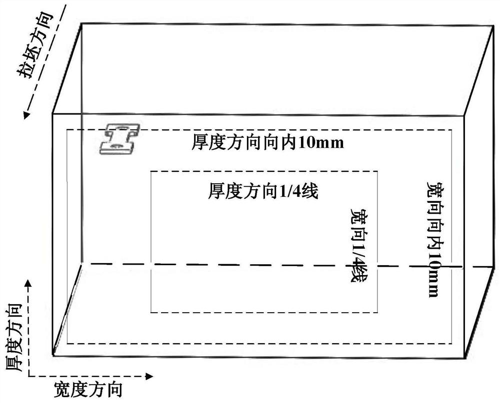
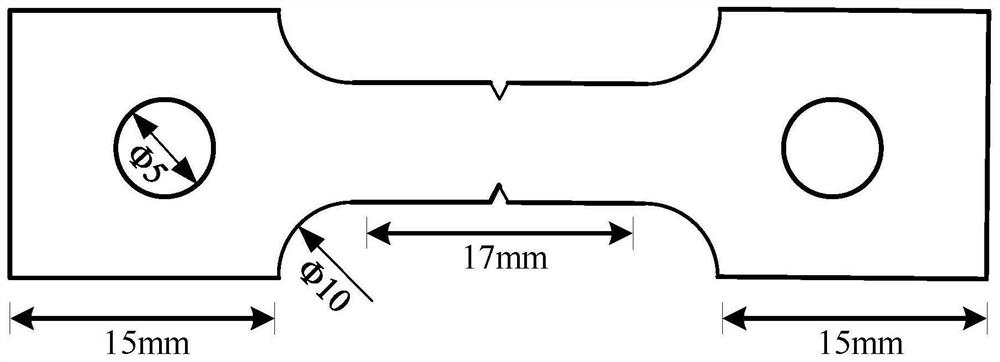
[0057] (1) Sampling
[0058] In order to avoid central segregation and serious porosity, samples were taken from the area formed between the thickness 1 / 4 line, the width 1 / 4 line and the distance from the surface of 10mm to obtain continuous casting slab samples; and the continuous casting slab samples were lined Cutting and turning to obtain the thin-section standard tensile specimen for the corner crack test (standard: the length of the specimen is 57mm, the thickness is 1.5mm, the gauge length is 17mm, the diameter of the sheath hole is Φ5, and the chamfer is Φ10). The schematic diagram of the sampling position is as follows figure 1 As shown, the obtained standard tensile specimens are prepared for tensile experiments;
[0059] (2) Prefabricated cracks
[0060] Because the obtained standard tensile specimen is thin-sheet ty...
Embodiment 2
[0075] A method for measuring the critical strain of crack propagation at the corner of a continuous casting slab, comprising the following steps:
[0076] (1) Sampling
[0077] In order to avoid central segregation and areas where porosity is more serious, the sample is sampled from the area formed between the thickness, width 1 / 4 line and the distance from the surface to 10mm to obtain the continuous casting slab sample. In this embodiment, the distance from the surface to the Sampling within 15mm;
[0078] Carry out wire cutting and turning processing on the continuous casting slab sample to obtain the standard tensile sample;
[0079] (2) Prefabricated cracks
[0080] It is used on a fatigue testing machine to prefabricate a V-shaped notch on a standard tensile sample by controlling the load or controlling the displacement. The depth is 0.5mm, and the notch angle is 35°. In order to understand the influence of sample surface roughness and small defects in the processing...
Embodiment 3
[0091] A method for measuring the critical strain of crack propagation at the corner of a continuous casting slab, the same as in Example 2, the difference is that:
[0092] (5) In the stress-strain curve of the specimen broken at the tensile temperature, the strain corresponding to the peak stress is the critical strain for crack propagation at the corner of the continuous casting slab.
[0093] By comparing the strain (Example 2) corresponding to the crack propagation in the metallographic photograph obtained during in-situ stretching and the strain value (Example 3) corresponding to the peak stress in the obtained stress-strain curve for consistency comparison, There is a difference of 0.005 between the two methods for determining the critical strain of crack propagation at the corner of the continuous casting slab, and the agreement is good.
PUM
| Property | Measurement | Unit |
|---|---|---|
| length | aaaaa | aaaaa |
| thickness | aaaaa | aaaaa |
Abstract
Description
Claims
Application Information
 - R&D
- Intellectual Property
- Life Sciences
- Materials
- Tech Scout
- Unparalleled Data Quality
- Higher Quality Content
- 60% Fewer Hallucinations
Browse by: Latest US Patents, China's latest patents, Technical Efficacy Thesaurus, Application Domain, Technology Topic, Popular Technical Reports.
© 2025 PatSnap. All rights reserved.Legal|Privacy policy|Modern Slavery Act Transparency Statement|Sitemap|About US| Contact US: help@patsnap.com