Three-dimensional scanning imaging processing equipment and method based on galvanometer
A technology of three-dimensional scanning and processing equipment, which is applied in the direction of metal processing equipment, welding equipment, laser welding equipment, etc., and can solve problems such as the inability to guarantee workpiece surface coincidence, human error, etc.
- Summary
- Abstract
- Description
- Claims
- Application Information
AI Technical Summary
Problems solved by technology
Method used
Image

Examples
Embodiment 1
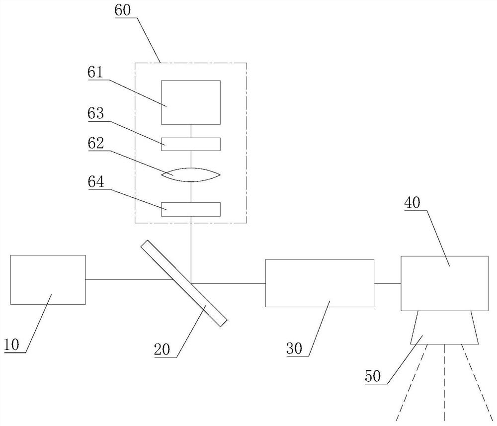
[0055] Please also refer to Figure 1 to Figure 4 , this embodiment provides a galvanometer-based three-dimensional scanning imaging processing equipment for processing workpieces based on photothermal effects, such as welding, cutting, engraving, surface modification, marking, drilling, and micromachining. This galvanometer-based three-dimensional scanning imaging processing device includes a light source 10 , a first optical mirror 20 , a first zoom lens 30 , a galvanometer mirror 40 , a focusing mirror 50 and a detection unit 60 . Wherein, the laser beam emitted by the light source 10 passes through the first optical mirror 20, the first zoom lens 30, the vibrating mirror 40, and the focusing mirror 50 in sequence, and then irradiates on the workpiece surface to form an incident optical path. The light reflected from the surface of the workpiece passes through the focusing mirror 50 , the vibrating mirror 40 , the first zoom lens 30 and the first optical mirror 20 in sequen...
Embodiment 2
[0074] see Figure 5 , the present embodiment provides a processing method using the above-mentioned galvanometer-based three-dimensional scanning imaging processing equipment, the specific steps are as follows:
[0075] S1, placing the workpiece, and correcting the vibrating mirror 40 and the first zoom lens 30 to zero.
[0076] The correction process refers to the 3D galvanometer format correction method.
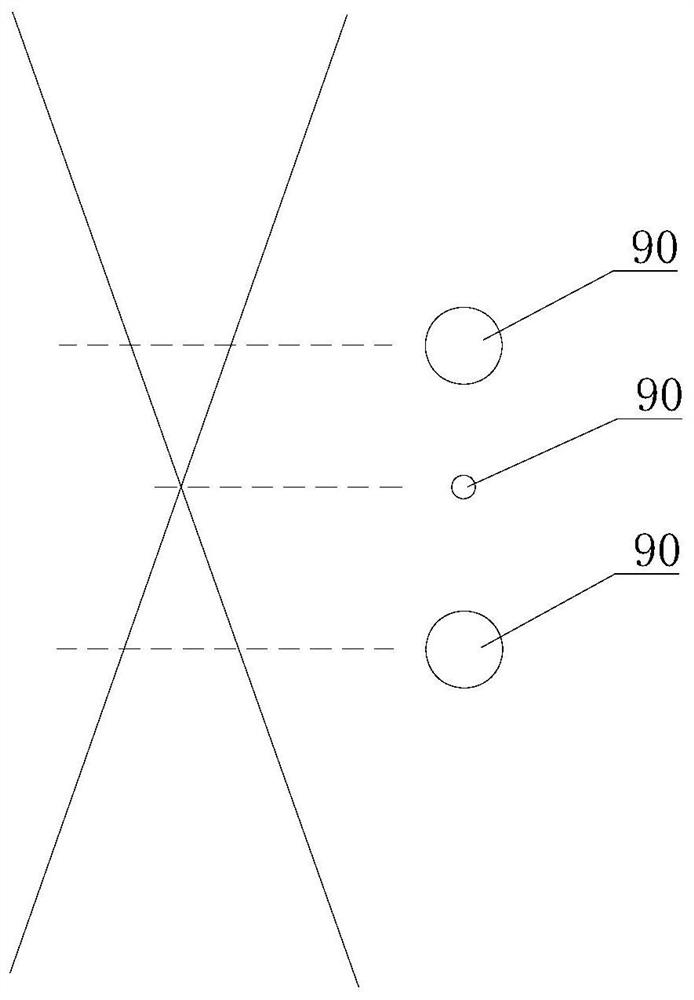
[0077] S2, causing the light source 10 to emit a first type of laser beam to irradiate the workpiece to form a light spot 90 .
[0078] The first kind of laser beam is a low-power laser beam used for scanning, after it passes through the first optical mirror 20, the first zoom lens 30, the vibrating mirror 40 and the focusing mirror 50 in sequence, it is irradiated on the workpiece surface along the third direction, and A light spot 90 is formed. Part of the reflected light at the light spot 90 passes through the focusing mirror 50 , the vibrating mirror 40 , the first...
Embodiment 3
[0090] see Image 6 , the present embodiment provides a three-dimensional scanning imaging processing device based on a vibrating mirror. The difference from Embodiment 1 is that this three-dimensional scanning imaging processing device based on a vibrating mirror further includes a second optical mirror 70 and a second zoom The lens 80 and the light source 10 are composed of a first laser 11 and a second laser 12 .
[0091] One side of the first optical mirror 20 that allows light to be reflected faces the first laser 11 , and the other side faces the detection unit 60 .
[0092] The second optical mirror 70 is a dichroic mirror, one side of which allows light to transmit, and the other side allows light to reflect. In addition, the second optical mirror 70 is parallel to the first optical mirror 20 and is located on the same side of the first optical mirror 20 as the first laser 11 . One side of the second optical mirror 70 that allows the reflection of light faces the fir...
PUM
 Abstract
Description
Claims
Application Information
 - R&D
- Intellectual Property
- Life Sciences
- Materials
- Tech Scout
- Unparalleled Data Quality
- Higher Quality Content
- 60% Fewer Hallucinations
Browse by: Latest US Patents, China's latest patents, Technical Efficacy Thesaurus, Application Domain, Technology Topic, Popular Technical Reports.
© 2025 PatSnap. All rights reserved.Legal|Privacy policy|Modern Slavery Act Transparency Statement|Sitemap|About US| Contact US: help@patsnap.com