
Low-speed motion control method and system applied to LCOS system phase modulation workbench

A technology of low-speed movement and phase modulation, which is applied to the photo-plate-making process of the pattern surface, the photo-plate-making process exposure device, optics, etc. Format light orientation and other issues

Pending Publication Date: 2021-05-18
SUZHOU UNIV +1
View PDF1 Cites 0 Cited by
  • Summary
  • Abstract
  • Description
  • Claims
  • Application Information

AI Technical Summary

Problems solved by technology

[0003] Patent application number CN201820881217.1 discloses a photo-alignment device for realizing arbitrary distribution in one exposure, and it introduces a photo-controlled alignment method using a pixelated electronically controlled phase delay device for a single exposure, wherein the pixelated electronically controlled phase delay device The phase delay of each pixel is controlled by the corresponding voltage, which is used to generate the phase delay of any pattern distribution, but the problem brought about by one exposure to generate the phase pattern is that the amount of data is proportional to the size of the format, which limits the preparation The format size of the device is also doomed to be unable to produce high-precision and high-resolution photo-alignment patterns
[0004] Foreign beam companies provide a device and method for optical alignment using continuous laser irradiation on LCOS phase modulation devices (De Sio L, Roberts D E, Liao Z, et al. Digital polarization holography advancing geometrical phase optics[J]. Optics express, 2016 , 24(16): 18297-18306.), they used a low-energy continuous laser for exposure. Considering the information content of the image, exposure uniformity, material heat capacity, thermal diffusion and other properties, it takes tens of seconds to expose a single field of view. It takes tens of minutes, and the exposure format is limited by the image information, so it is impossible to perform photo-orientation on a large-area format

Method used


Image

  • Low-speed motion control method and system applied to LCOS system phase modulation workbench
  • Low-speed motion control method and system applied to LCOS system phase modulation workbench
  • Low-speed motion control method and system applied to LCOS system phase modulation workbench

Examples


Embodiment Construction

[0040] In order to make the purpose, technical solutions and advantages of the present invention clearer, the technical solutions in the embodiments of the present invention will be clearly and completely described below in conjunction with the accompanying drawings in the embodiments of the present invention. Obviously, the described embodiments are only Some, but not all, embodiments of the invention. Based on the embodiments of the present invention, all other embodiments obtained by persons of ordinary skill in the art without making creative efforts belong to the protection scope of the present invention.

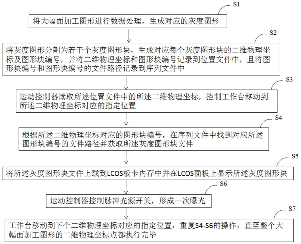
[0041] On the one hand, the embodiment of the present invention discloses a low-speed motion control method applied to the phase modulation workbench of the LCOS system, such as figure 1 As shown, the low-speed motion control method includes the following steps:

[0042] S1. Perform data processing on the large-format processed graphics to generate corresponding gray-...


PUM


Abstract

The invention discloses a low-speed motion control method applied to a phase modulation workbench of an LCOS system, which comprises the following steps: carrying out data processing on a large-format processing graph and dividing the large-format processing graph into a plurality of graph blocks, and controlling the workbench to move to a specified position corresponding to a two-dimensional physical coordinate by a motion controller; uploading the graphic block file to an LCOS board card memory, and displaying the graphic block file on an LCOS panel; enabling the motion controller to control a pulse light source switch to form primary exposure; and enabling the workbench to move to a designated position corresponding to the next two-dimensional physical coordinate until the two-dimensional physical coordinate points of the whole large-format processing graph are executed. According to the invention, the characteristics of large pulse laser energy, short pulse width and high repetition frequency are utilized, single-frame polarization pattern recording is realized based on a single pulse, and the advantages of large exposure area, high efficiency and good reliability are realized by accurately controlling the movement of the workbench.

Description

technical field [0001] The invention relates to the field of liquid crystal orientation alignment control, in particular to a low-speed motion control method and system applied to a phase modulation workbench of an LCOS system. Background technique [0002] The polarization orientation technology based on the liquid crystal spatial modulator is a programmable control device that can modulate the phase and amplitude of the incident light. A single projection orientation can realize the pattern recording of different orientations of liquid crystals in different selected areas. [0003] Patent application number CN201820881217.1 discloses a photo-alignment device for realizing arbitrary distribution in one exposure, and it introduces a photo-controlled alignment method using a pixelated electronically controlled phase delay device for a single exposure, wherein the pixelated electronically controlled phase delay device The phase delay of each pixel is controlled by the correspo...

Claims


Application Information

Patent Timeline
Patent Type & Authority Applications(China)
IPC IPC(8): G02F1/1337G03F7/20
CPCG02F1/133788G03F7/70358
Inventor 黄文彬张新君郑致刚王骁乾
Owner SUZHOU UNIV
Learn More