A Fiber Bragg Grating Pressure Sensor Packaged in Carbon Fiber Tube
A technology of pressure sensor and optical fiber grating, which is applied in the direction of fluid pressure measurement by optical method, measurement of fluid pressure, and measurement of the change force of optical properties of materials when they are stressed. It can solve the problems of high sensitivity, low sensitivity, low range and other issues, to achieve the effect of simple preparation process, wide application prospects, and low preparation cost
- Summary
- Abstract
- Description
- Claims
- Application Information
AI Technical Summary
Problems solved by technology
Method used
Image
Examples
Embodiment 1
[0024] The invention discloses a fiber grating pressure sensor packaged in a carbon fiber tube, which includes a carbon fiber tube, a package body, and an optical fiber. The schematic diagram of its structure is as follows figure 1 shown. The fiber grating sensor includes a temperature compensation grating 1, a cylindrical package 2, a hollow steel pipe 3, a U-shaped package 4, a T-shaped package 5, a thread 6, a carbon fiber tube 7, a pressure-sensitive grating 8, a carbon fiber sheet 9 and an optical fiber 10. In this embodiment, the temperature compensation grating 1 is packaged in the hollow steel pipe 3 through the cylindrical package 2, and the U-shaped package 4, the T-shaped package 5 and the carbon fiber tube 7 are packaged with high-temperature-resistant epoxy resin glue , forming the base elastomer.
[0025] Preferably, the carbon fiber tube 7 in this embodiment is braided using a three-dimensional and four-directional braiding process, and the material is carbon f...
Embodiment 2
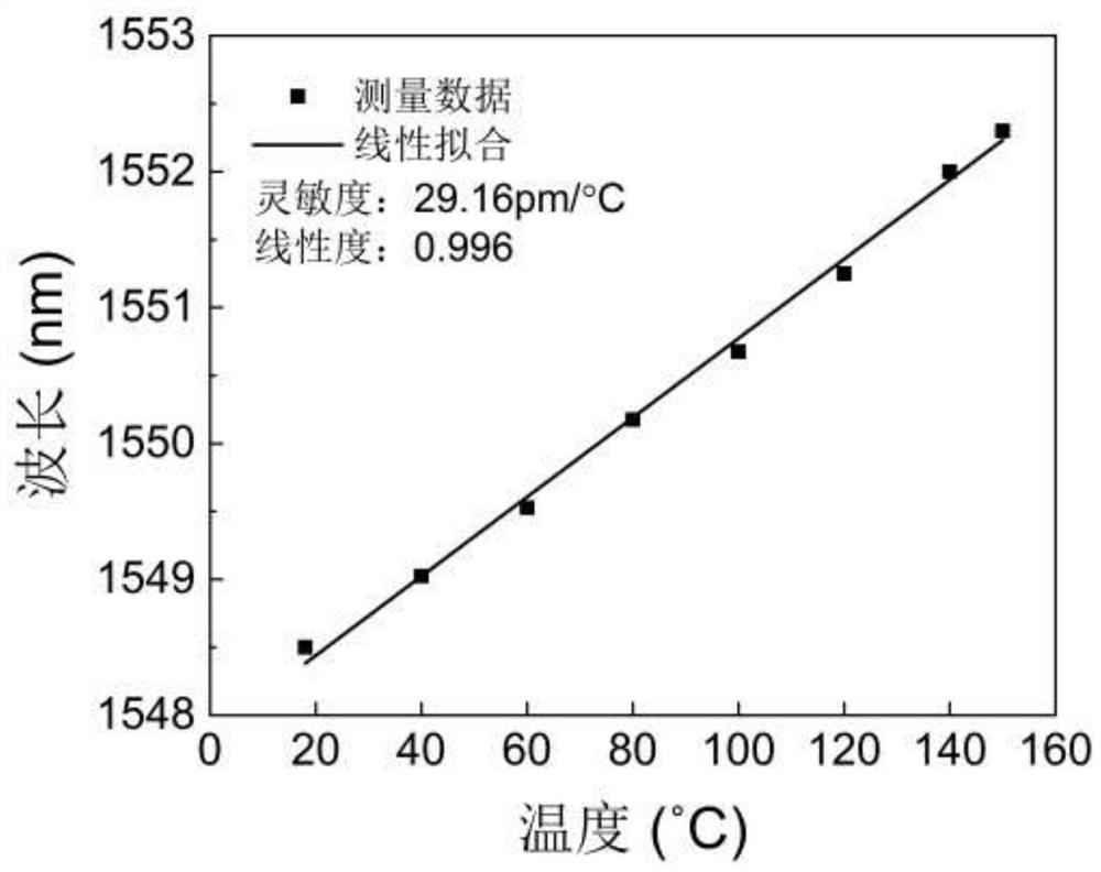
[0032] This embodiment provides a temperature response testing method of a fiber grating pressure sensor packaged in a carbon fiber tube, comprising the following steps:
[0033] (1) Connect one end of the packaged pressure sensor to a fiber optic coupler, and connect the other two ends of the fiber optic coupler to a broadband light source (Superk Compact, NKT Photonics, Denmark) and a spectrum analyzer (AQ6370B, Yokogawa, Japan). The broadband light source outputs supercontinuum light, and the spectrum analyzer is used to monitor the reflection spectrum, and its wavelength resolution is set to 20pm, and the wavelength scanning range is 1500-1600nm.
[0034] (2) Place the packaged pressure sensor in a constant temperature oil tank (HTS-30B) for heating. The temperature resolution of the constant temperature oil tank is ±0.01°C. The temperature characteristics were demonstrated at 20°C intervals between room temperature and 150°C, and the temperature of the oil tank was kept c...
Embodiment 3
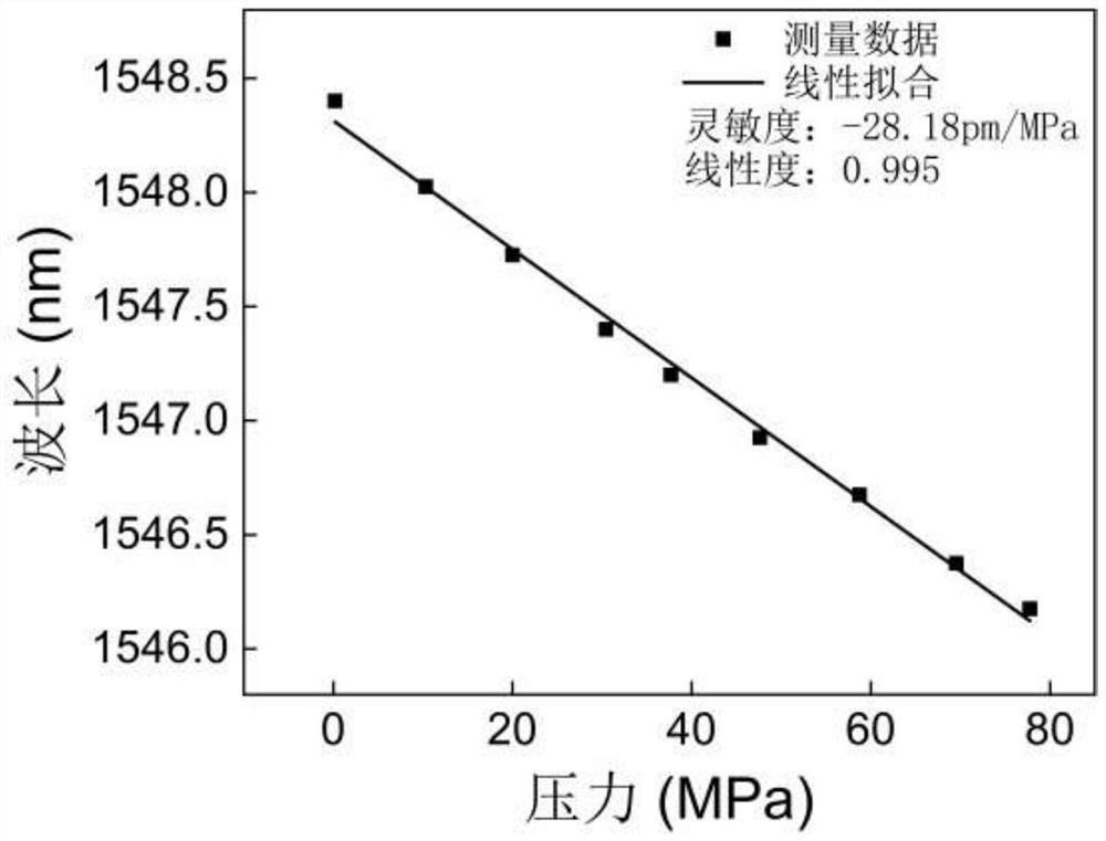
[0042] A pressure response test of a fiber grating pressure sensor packaged in a carbon fiber tube at high temperature, comprising the following steps:
[0043] (1)(2) Same as pressure response test at room temperature.
[0044] (3) Put the high-pressure tank in the constant temperature oil tank (HTS-30B), at the temperature of 50°C, 100°C, and 150°C respectively, the pressure increases from 0MPa to 80MPa at unequal intervals, and the pressure fluctuation during data recording is <± 0.05MPa.
[0045] Figure 4 It is the pressure response curve of the pressure-sensitive grating of the fiber grating pressure sensor packaged in a carbon fiber tube of the present invention at different temperatures. The pressure response characteristics of the pressure sensor at 50°C, 100°C, and 150°C were studied. The sensitivities at ℃, 100℃, and 150℃ are -29.55pm / MPa, -30.91pm / MPa, and -50.02pm / MPa, respectively, and the pressure response and pressure-sensitive grating wavelength change show ...
PUM
| Property | Measurement | Unit |
|---|---|---|
| elastic modulus | aaaaa | aaaaa |
| elastic modulus | aaaaa | aaaaa |
| length | aaaaa | aaaaa |
Abstract
Description
Claims
Application Information
 - R&D
- Intellectual Property
- Life Sciences
- Materials
- Tech Scout
- Unparalleled Data Quality
- Higher Quality Content
- 60% Fewer Hallucinations
Browse by: Latest US Patents, China's latest patents, Technical Efficacy Thesaurus, Application Domain, Technology Topic, Popular Technical Reports.
© 2025 PatSnap. All rights reserved.Legal|Privacy policy|Modern Slavery Act Transparency Statement|Sitemap|About US| Contact US: help@patsnap.com


