
Turbine guider blade cooling device with low-melting-point metal as flowing working medium

A technology for turbine guides and low-melting-point metals, applied in the direction of blade support components, engine components, engine functions, etc., can solve the problem of reducing engine thermal efficiency and working ability, increasing aerodynamic loss of main gas flow, and aggravating heat loss of main gas flow and other problems, to achieve the effect of increasing propulsion power, prolonging service life and improving strength

Active Publication Date: 2021-05-14
BEIHANG UNIV
View PDF9 Cites 5 Cited by
  • Summary
  • Abstract
  • Description
  • Claims
  • Application Information

AI Technical Summary

Problems solved by technology

However, the cooling air quoted is drawn from the compressor. In order to meet the cooling demand, the opportunity to do work is lost, which greatly reduces the thermal efficiency and work ability of the engine; During the thermal protection process, the components absorb heat from the main gas flow, which intensifies the heat loss in the main gas flow. After mixing with the main gas flow, it is easy to cause the unstable flow of the air flow and increase the aerodynamic loss of the main gas flow.

Method used


Image

  • Turbine guider blade cooling device with low-melting-point metal as flowing working medium
  • Turbine guider blade cooling device with low-melting-point metal as flowing working medium
  • Turbine guider blade cooling device with low-melting-point metal as flowing working medium

Examples


Embodiment Construction

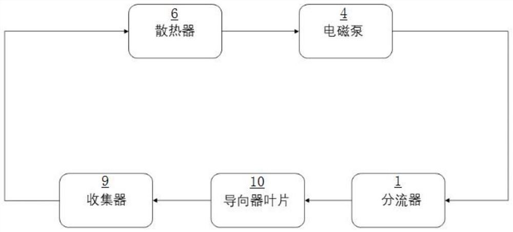
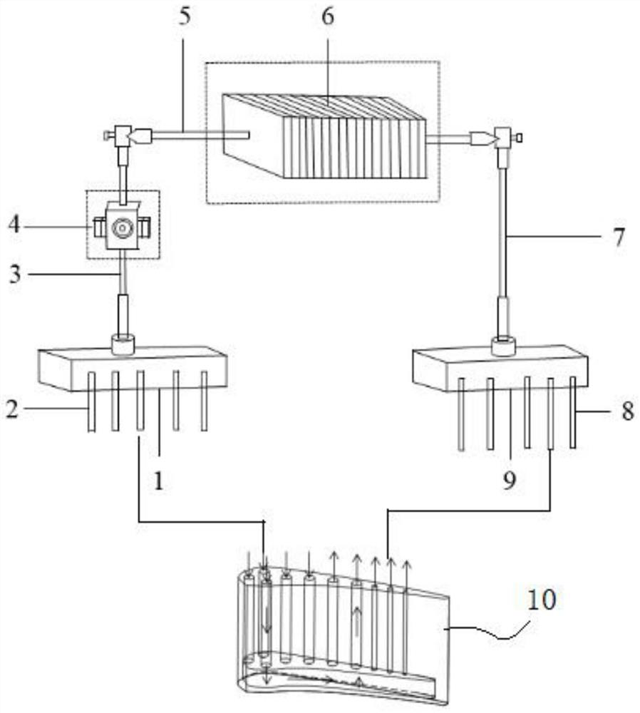
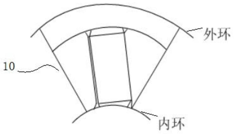
[0030] figure 1 It is a schematic logic control diagram of a turbine guide vane cooling device using a low-melting point metal as a working medium according to an embodiment of the present application. figure 2 It is a schematic structural diagram of a turbine guide vane cooling device in which the low-melting point metal in the outer part of the guide vane outer ring is used as a working medium. image 3 is a schematic structural diagram of a guide vane. Figure 4 is a schematic perspective view of the guide vane.

[0031] Such as Figure 4 As shown, in this embodiment, multiple cooling passages are arranged in the guide vane 10 . A cavity 13 is reserved at a bottom position inside the deflector vane 10 . Each cooling channel communicates with said chamber 13 . Part of the cooling passages in the plurality of cooling passages are cooling passages 11 that flow into the blade, and the rest of the cooling passages in the plurality of cooling passages are cooling passages 1...


PUM


Abstract

The invention discloses a turbine guider blade cooling device with low-melting-point metal as a flowing working medium, and relates to guider blade cooling. A plurality of cooling channels and cavities are arranged in a guider blade. The turbine guider blade cooling device with the low-melting-point metal as the flowing working medium comprises a flow divider, a collector, a radiator and an electromagnetic pump, wherein the electromagnetic pump and the guider blade form a closed loop, liquid low-melting-point metal or alloy thereof is driven by the electromagnetic pump to serve as the flowing working medium to circularly flow in the closed loop, and rapid heat dissipation is achieved through the radiator. According to the turbine guider blade cooling device with the low-melting-point metal as the flowing working medium, air cooling is not adopted, cooling air originally led out from a gas compressor is saved, and the propelling power of an aircraft is increased; the cooling effect is far better than that of a gas cooling mode in a traditional process, the heat transfer efficiency is high, and the temperature drop of the guider blade is larger, so that the service life of the guider blade is prolonged; air film holes do not need to be formed in the outer surface of the guider blade, and the strength of the blade is improved; the whole process is cyclically closed, the low-melting-point metal or the alloy thereof is recycled, and the environment is not affected.

Description

technical field [0001] The application relates to a cooling device for a turbine guide vane of an aviation gas turbine engine, in particular to a cooling device for cooling a turbine guide vane using a low-melting point metal or an alloy thereof as a working medium. Background technique [0002] In order to improve the thrust-to-weight ratio and thermal efficiency of aviation gas turbine engines, it is necessary to achieve the design goals by increasing the total pressure ratio and turbine inlet temperature. Especially the increase of turbine inlet temperature directly affects the efficiency of the engine. At present, the inlet temperature of the turbine has reached as high as 1800-2050K. At such a high temperature, higher requirements are put forward for the heat resistance of various parts of the turbine. On the one hand, it is necessary to develop new heat-resistant materials; on the other hand, it is necessary to take protective measures for hot-end components through a...

Claims


Application Information

Patent Timeline
Patent Type & Authority Applications(China)
IPC IPC(8): F01D25/12F01D9/02
CPCF01D25/12F01D9/02F01D5/181F05D2260/208F05D2260/232F01D9/065F01D9/041F05D2240/126F05D2240/128F05D2260/205F05D2260/213F05D2260/22141
Inventor 罗翔张哲邬泽宇
Owner BEIHANG UNIV
Learn More