Cutting device for steel plate machining

A technology for cutting devices and steel plates, applied in positioning devices, metal processing equipment, metal processing machinery parts, etc., can solve problems affecting cutting effects, air pollution, and unfavorable health of workers

Active Publication Date: 2021-05-14
浙江天羿钢结构有限公司
View PDF13 Cites 0 Cited by
  • Summary
  • Abstract
  • Description
  • Claims
  • Application Information

AI Technical Summary

Problems solved by technology

When processing steel plates, it needs to be cut. Generally, the material is fed manually and cut with a cutter. The steel plate is easy to shift, which affects the cutting effect, and the dust is flying during cutting, causing certain air pollution, which is not conducive to the health of workers.

Method used


Image

  • Cutting device for steel plate machining
  • Cutting device for steel plate machining
  • Cutting device for steel plate machining

Examples


Embodiment 2

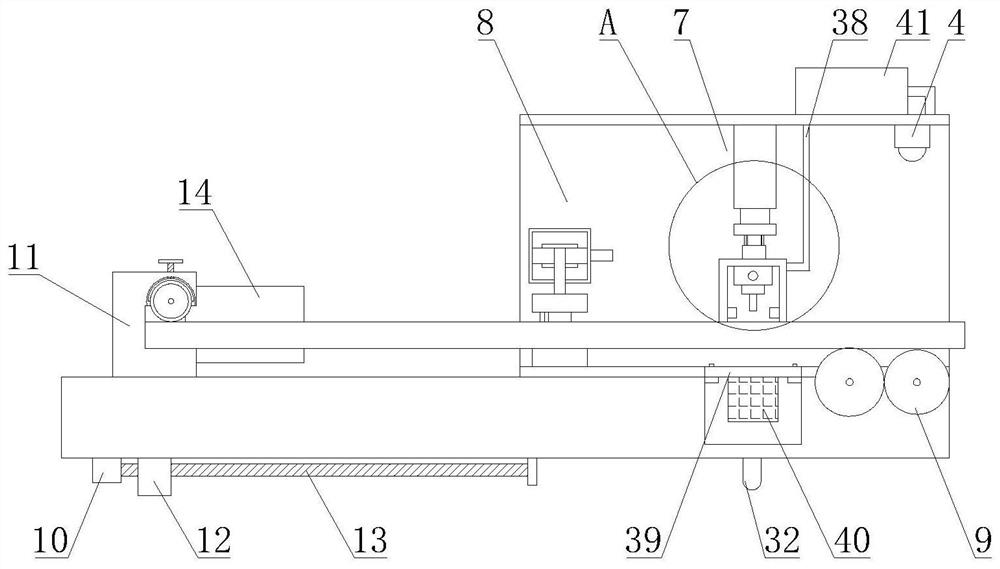
[0050] Such as Figure 8-10 As shown, a positioning assembly 8 is also included; the positioning assembly 8 is arranged between the feeding assembly 6 and the dustproof assembly 7, and includes a mounting frame 42, a fourth driving motor 43, a rotating shaft 44, a rotating belt 45, a positioning member 46 and a connecting member 47; the mounting frame 42 is arranged inside the cutting chamber 2, and spans above the steel plate; two sets of rotating shafts 44 transmitted by the fourth driving motor 43 are arranged, and the two groups of rotating shafts 44 are rotated and arranged at both ends of the mounting frame 42; Belt 45 is sleeved on two groups of rotating shafts 44, and rotates synchronously with it; Two groups of connectors 47 are arranged, and two groups of connectors 47 connect the upper stratum and the lower floor of rotating belt 45 respectively; 47 one-to-one correspondence connections.

[0051] In an optional embodiment, the positioning member 46 includes an uppe...

Embodiment 3

[0055] The present invention proposes a kind of steel plate cutting method again, and the steps are as follows:

[0056] S1, place the steel plate on the console 1;

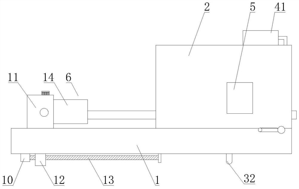
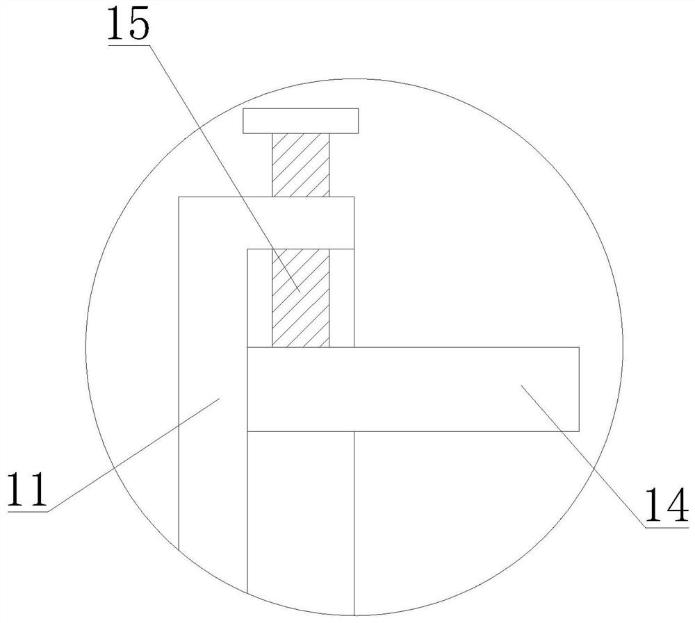
[0057] S2. Clamp one end of the steel plate in the first engaging groove of the feeding assembly 6, rotate the first threaded rod 15, and move the second engaging frame 14 towards the steel plate until both sides thereof are locked in the second engaging groove, At the same time, the fixing member 16 is operated, so that the fixing plate 18 blocks the anti-skid wheel 17;

[0058] S3, operate the positioning assembly 8, the rotating belt 45 rotates, drives the positioning member 46 to move towards the steel plate, lifts the steel plate, makes it placed on the lower positioning plate 49, and engages with the rotating roller 50;

[0059] S4, the feeding assembly 6 works, the first driving motor 10 drives the first lead screw 13 to rotate, the first engaging frame 11 moves toward the cutting chamber 2 at a constant ...


PUM

PropertyMeasurementUnit
widthaaaaaaaaaa

Abstract

The invention discloses a cutting device for steel plate machining, and relates to the field of steel plate machining. The cutting device for the steel plate machining comprises an operation table, a cutting chamber, a cutter, automatic measuring equipment, a controller, a moving roller, a feeding assembly and a dustproof assembly; the cutting chamber is arranged on the operation table, and a feeding end and a discharging end are open; the moving roller is rotationally arranged on the operation table; the cutter and the automatic measuring equipment are arranged in the cutting chamber; the feeding assembly is arranged on the operation table and is close to the feeding end of the cutting chamber; the dustproof assembly is arranged on the cutter. According to the cutting device for the steel plate machining, the feeding assembly is arranged to fix a steel plate, a stable state of the steel plate in the cutting process is guaranteed, a cutting error is reduced, automatic feeding is achieved, and the working efficiency is improved; the dustproof assembly avoids dust flying, waste water is recycled, and environment-friendly and energy-saving purposes are achieved; a positioning assembly is arranged to position a cutting end of the steel plate, a steel plate moving track is guaranteed, and cutting accuracy is improved.

Description

technical field [0001] The invention relates to the field of steel plate processing, in particular to a cutting device for steel plate processing. Background technique [0002] The steel plate is a flat steel material that is poured with molten steel and pressed after cooling. The width of the thin plate is 500-1500 mm; the width of the thick plate is 600-3000 mm. Sheets are classified by steel type, including ordinary steel, high-quality steel, alloy steel, spring steel, stainless steel, tool steel, heat-resistant steel, bearing steel, silicon steel, and industrial pure iron sheets, etc.; by professional use, there are plates for oil drums, Enamel plates, bulletproof plates, etc.; according to the surface coating, there are galvanized sheets, tinned sheets, lead-plated sheets, plastic composite steel sheets, etc. When steel plate is processed, it needs to be cut. Generally, the material is fed manually and cut with a cutter. The steel plate is easy to shift, which affects...

Claims


Application Information

Patent Timeline
Patent Type & Authority Applications(China)
IPC IPC(8): B23D79/00B23Q3/06B23Q11/00B23Q17/20
CPCB23D79/00B23Q3/062B23Q17/20B23Q11/0042Y02P70/10
Inventor 黄秋霞
Owner 浙江天羿钢结构有限公司
Why Eureka
Try Eureka