Eureka AIR delivers breakthrough ideas for toughest innovation challenges, trusted by R&D personnel around the world.

Clamping tool and method for adhesive connection of metal bipolar plates of fuel cells

A metal bipolar plate and fuel cell technology, applied in the field of fixtures, can solve the problems of increasing the difficulty of surface coating preparation, virtual welding, low efficiency, etc., to simplify the initial clamping process, avoid warping deformation, simplify the The effect of the overall process

Pending Publication Date: 2021-05-07
SHANGHAI ZHIZHEN NEW ENERGY EQUIP CO LTD
View PDF0 Cites 0 Cited by
  • Summary
  • Abstract
  • Description
  • Claims
  • Application Information

AI Technical Summary

Problems solved by technology

[0003] The existing laser welding processing method can not be realized on one tooling plate because the sub-field path will form a closed loop. When making the welding tooling, it can be realized by at least two weldings. This method requires the metal bipolar plate The secondary clamping will affect the positioning and working time, and the efficiency is low
In addition, due to the uneven thermal shrinkage of the laser-welded area, the metal bipolar plate that has been laser-welded will warp irregularly. The reliability of stacked assembly of plates; laser welding oxidizes the surface, which increases the difficulty of surface coating preparation; it is also prone to false welding, which seriously restricts the yield

Method used


Image

  • Clamping tool and method for adhesive connection of metal bipolar plates of fuel cells
  • Clamping tool and method for adhesive connection of metal bipolar plates of fuel cells
  • Clamping tool and method for adhesive connection of metal bipolar plates of fuel cells

Examples


Embodiment Construction

[0047] The specific embodiments of the present invention will be described in detail below in conjunction with the accompanying drawings, so that those skilled in the art can more clearly understand how to practice the present invention. While the invention has been described in connection with preferred specific embodiments thereof, these embodiments are illustrative only and are not intended to limit the scope of the invention.

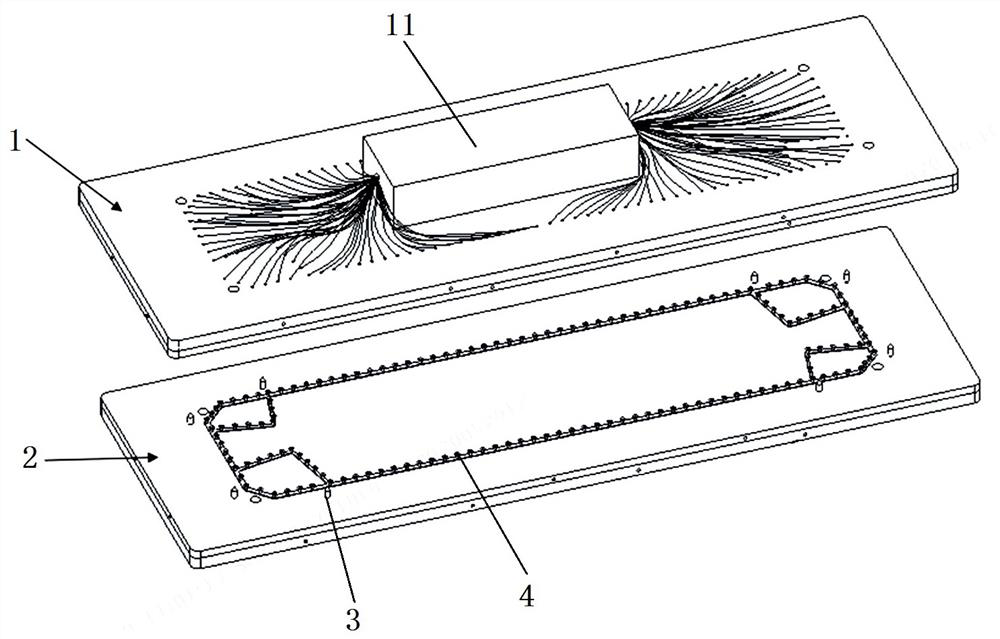
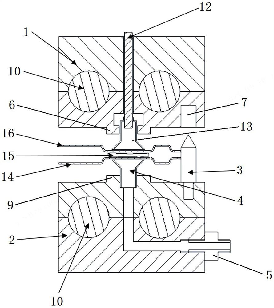
[0048] A clamping tool for adhesive connection of metal bipolar plates of a fuel cell comprises a positioning device, a heating device and a vibration device.

[0049] The positioning device is used to fix the posture of the polar plate. see figure 1 with figure 2 , The positioning device mainly includes a tooling upper cover plate 1, a tooling lower plate 2, a positioning pin 3, a first suction nozzle 4, a gas pipe joint 5, and a vacuum pump.

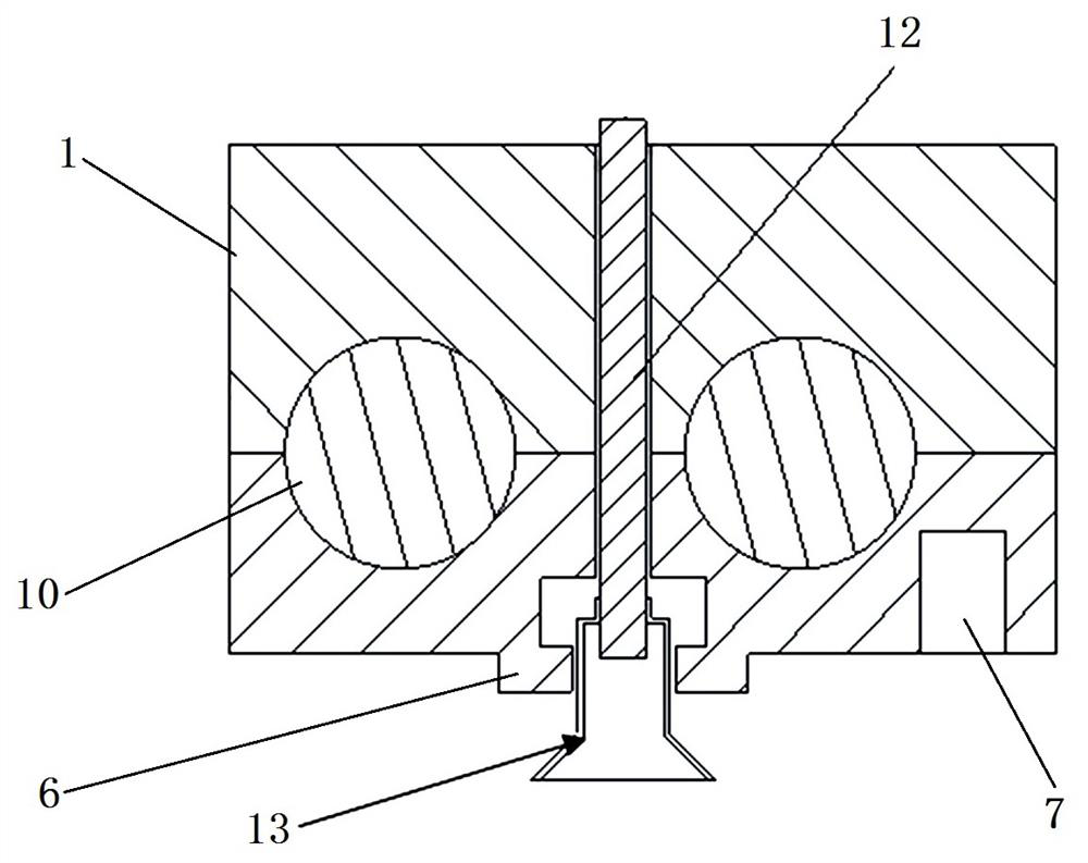
[0050] see image 3 The tooling upper cover plate 1 is formed by connecting two first tooling plates...


PUM


Abstract

The invention relates to a clamping tool and method for adhesive connection of metal bipolar plates of fuel cells. The clamping tool comprises a positioning device, a heating device and a vibration device. The positioning device comprises a tool upper cover plate, a tool lower bottom plate, positioning pins and first suction nozzles. The vibration device comprises a vibration source, vibration conductors and second suction nozzles. The heating device is arranged in the tool upper cover plate and the tool lower bottom plate. The vibration conductors penetrate through the tool upper cover plate, the upper ends of the vibration conductors are connected with the vibration source, and the lower ends of the vibration conductors are connected with the second suction nozzles. Vacuumizing channels are formed in the tool lower bottom plate, the upper ends of the vacuumizing channels are connected with the first suction nozzles, and the lower ends of the vacuumizing channels are communicated with the side face of the tool lower bottom plate. The tool upper cover plate and the tool lower bottom plate are adopted to clamp the metal bipolar plates, one-time clamping is adopted, the risk of polar plate dislocation caused by secondary clamping is avoided, and the initial clamping process of the metal bipolar plates is simplified. Full-automatic circulation is adopted in the forming process, the overall technology is simplified, and the phenomenon of polar plate buckling deformation caused by original laser welding is avoided.

Description

technical field [0001] The invention belongs to the technical field of tooling fixtures, in particular to a clamping tooling and a method for adhesively connecting metal bipolar plates of fuel cells. Background technique [0002] Fuel cells generate electricity through the electrochemical reaction of hydrogen and oxygen, and the final product is water, which is an important part of the current pollution-free and zero-emission new energy. The existing metal bipolar plates mainly connect the anode unipolar plate and the cathode unipolar plate by laser welding to form a structure of “two plates and three fields”. [0003] The existing laser welding processing method can not be realized on one tooling plate because the sub-field path will form a closed loop. When making the welding tooling, it can be realized by at least two weldings. This method requires the metal bipolar plate The secondary clamping will affect the positioning and working time, and the efficiency is low. In ...

Claims


Application Information

Patent Timeline
IPC IPC(8): B25B11/02F16B11/00
CPCB25B11/02F16B11/006
Inventor 姜天豪曹运毕飞飞胡鹏杜祥永蓝树槐
Owner SHANGHAI ZHIZHEN NEW ENERGY EQUIP CO LTD
Why Eureka
Eureka Blog
Learn More