
Hollow tungsten electrode coaxial wire filling welding device and regulating and welding method

A technology of welding device and tungsten electrode, which is applied in hollow tungsten electrode coaxial filler wire welding device and control and welding fields, can solve the problems of welding process stability and process controllability cannot be guaranteed, assembly problems and conductive uniformity problems cannot be solved. It is solved, without considering the uniformity of gas feeding, etc., to achieve the effect of improving deposition efficiency, eliminating directional problems, and improving welding quality

Pending Publication Date: 2021-05-04
HARBIN WELDING INST LTD
View PDF2 Cites 7 Cited by
  • Summary
  • Abstract
  • Description
  • Claims
  • Application Information

AI Technical Summary

Problems solved by technology

The invention patent with the patent number CN201710512517.2 realizes the insulation between the tungsten electrode and the welding wire by coating the inner wall of the two half-split tungsten electrodes with an insulating layer, and then combines the two half-split tungsten electrodes into one tungsten electrode. Finally, the purpose of coaxial tungsten electrode and welding wire is achieved, but this method increases the difficulty of the welding process, and the assembly problem between the two tungsten electrodes and the uniformity of conductivity cannot be solved; the patent No. 201610998677.8 provides a Hollow tungsten electrode coaxial wire-filled TIG welding device and its welding torch. This patent sends the welding wire out from the inner hole of the hollow tungsten electrode, and connects the inner hole of the tungsten electrode with the shielding gas cavity by drilling holes in the side wall of the tungsten electrode. The effect of combined gas-wire feeding is realized, but this method does not take into account the uniformity of gas feeding and the insulation between the welding wire and the inner hole of the tungsten electrode. At the same time, the phenomenon of conduction makes the stability of the welding process and the controllability of the process unable to be guaranteed.

Method used


Image

  • Hollow tungsten electrode coaxial wire filling welding device and regulating and welding method
  • Hollow tungsten electrode coaxial wire filling welding device and regulating and welding method
  • Hollow tungsten electrode coaxial wire filling welding device and regulating and welding method

Examples


Embodiment 1

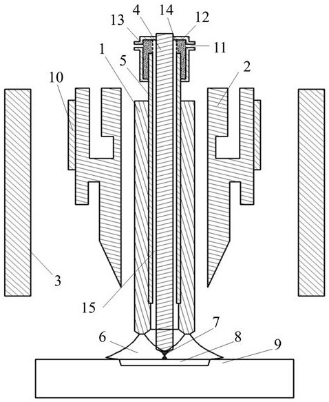
[0055] A hollow tungsten pole coaxial wire filling welding device, the hollow tungsten pole coaxial wire filling welding device comprises a hollow tungsten pole 1, a tungsten pole clamp 2, a protective gas cover 3, a welding wire 4, an insulating porcelain tube 5, and an ion buffer filter Air chamber 12;

[0056] The hollow tungsten electrode is clamped by symmetrically arranged tungsten electrode holders, the protective gas cover is located outside the tungsten electrode holder, and the plasma buffer and filter air chamber is fixed on the upper end of the hollow tungsten electrode;

[0057] There is a step in the hollow tungsten pole, the insulating porcelain tube is inserted into the step in the hollow tungsten pole, the welding wire is inserted in the insulating porcelain tube, and the welding wire and the The gap between the hollow tungsten electrodes forms an ion gas channel 15;

[0058] The gas passes through the ion gas channel and passes through the porous material in...

Embodiment 2

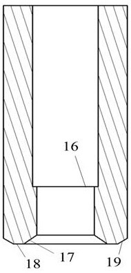
[0064] According to the hollow tungsten pole coaxial wire-filled welding device described in Embodiment 1, the bottom of the hollow tungsten pole is a bell mouth, and the end face is circular, cut along the radial direction, and divided into multiple arc emission points. Hollow tungsten pole with stepped petals.

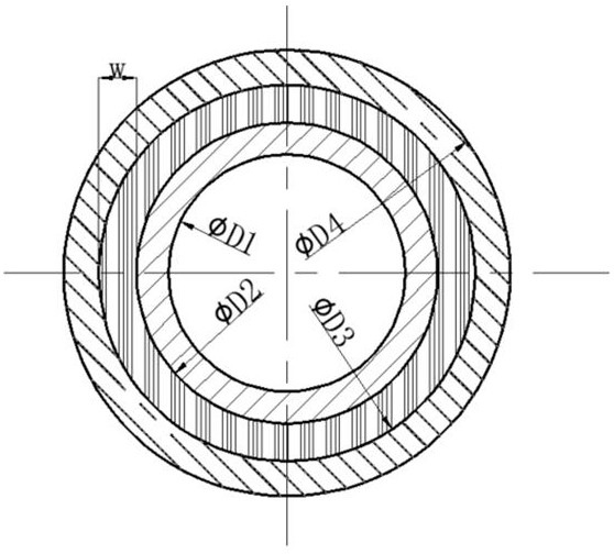
[0065] The shape of the hollow tungsten electrode electron emission end includes three parts: ①The inner hole of the hollow tungsten electrode electron emission end with an outer diameter of D1 and an inner hole diameter of D4 is processed into a bell mouth shape with a certain angle. The inner surface of the bell mouth is called the inner wall. The diameter of the inner wall is D2; ②A bevel with a certain chamfer is processed on the outer diameter of the hollow tungsten electron emission end, and the torus formed by the inclination is called the outer wall; ③The unprocessed end face of the electron emission end is used for emission Electrons, the end face is called ...

Embodiment 3

[0068] According to the hollow tungsten electrode coaxial wire-filling welding device described in embodiment 1 or 2, the step of the inner step hole processing of the stepped petal hollow tungsten electrode is located 10-20 mm above the end of the hollow tungsten electrode.


PUM

PropertyMeasurementUnit
widthaaaaaaaaaa
electrical resistivityaaaaaaaaaa
diameteraaaaaaaaaa

Abstract

The invention discloses a hollow tungsten electrode coaxial wire filling welding device and a regulating and welding method. An existing hollow tungsten electrode coaxial wire filling welding technology is still low in welding efficiency. The hollow tungsten electrode coaxial wire filling welding device comprises a hollow tungsten electrode (1), tungsten electrode clamps (2), a protective gas hood (3), a welding wire (4), an insulating porcelain tube (5) and a plasma buffering and filtering gas chamber (12); the hollow tungsten electrode is clamped by the symmetrically-arranged tungsten electrode clamps; the protective gas hood is located on the outer sides of the tungsten electrode clamps; and the plasma buffering and filtering gas chamber is fixed to the upper end of the hollow tungsten electrode; a step is arranged in the hollow tungsten electrode; the insulating porcelain tube is inserted into the step in the hollow tungsten electrode; a welding wire is inserted into the insulating porcelain tube; a gap between the welding wire and the hollow tungsten electrode forms an ion gas channel (15); an ion gas filter screen (14) is fixed in the plasma buffering and filtering gas chamber; and a porous medium material (13) is filled in a closed space formed by the ion gas filter screen and the plasma buffering and filtering gas chamber. The method is used for core tungsten electrode coaxial wire filling regulation and welding.

Description

technical field [0001] The invention relates to a hollow tungsten pole coaxial filler wire welding device and a control and welding method. Background technique [0002] With its unique process stability, the traditional argon tungsten arc side-axis welding technology has always been the preferred technology for high-quality welding solutions in certain fields, and it has played its irreplaceable and unique role in many key areas of promoting national economic development. effect. However, the traditional argon tungsten arc welding side-axis wire-filled welding technology has a large space for the welding torch, limited arc heat for effectively melting the welding wire, high dilution rate of the deposited layer, directional process implementation, and poor welding protection effect for non-ferrous metals And other shortcomings, so that it has great limitations in the application of welding or arc additive manufacturing of special materials and complex structural parts. [...

Claims


Application Information

Patent Timeline
Patent Type & Authority Applications(China)
IPC IPC(8): B23K9/167B23K9/133B23K9/32
CPCB23K9/133B23K9/167B23K9/32
Inventor 杨义成黄瑞生陈健杜兵徐锴费大奎孙谦方迪生张炎于丹邹吉鹏刘孔丰
Owner HARBIN WELDING INST LTD
Learn More