Thin-wall diamond anti-cracking cutting device
A cutting equipment and diamond technology, applied in the field of thin-walled diamond anti-cracking cutting equipment, can solve the problems affecting processing quality, yield to be improved, diamond plate cracking, etc., to improve product quality, facilitate recycling operations, and reduce labor Effect
- Summary
- Abstract
- Description
- Claims
- Application Information
AI Technical Summary
Problems solved by technology
Method used
Image

Examples
Embodiment 1
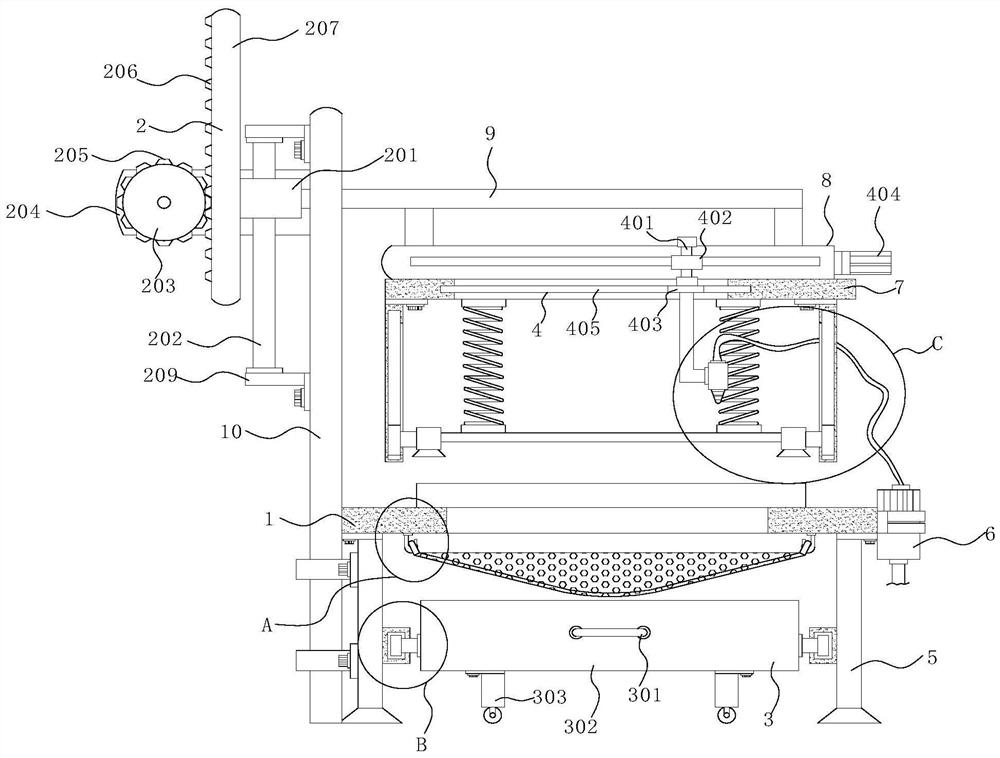
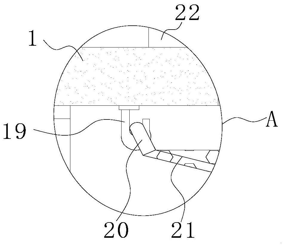
[0032]SeeFigure 1-10, A thin-walled diamond anti-crack cutting apparatus, including the operation board 1, the bottom of the operation plate 1 fixes four sets of support legs, and the bottom of the four sets of support legs are provided with rubber non-slip pedestal for non-slip, and the operation panel 1 The collecting mechanism 3 is provided below, and the top portion of the operation panel 1 is fixedly mounted, and the opening 23 is provided on the operation plate 1, and the opening 23 is located inside the placed seat 22, and four sets of hooks 19 are fixedly mounted at the bottom of the operating plate 1. The end of the operation board 1 is provided with a net pocket 21, and the two angles of the net pocket 21 are fixedly connected to the ring 20, the ring 20 is set to the hook 19, which makes the net pocket 21 can perform very convenient disassembly cleaning, easy to use On one side of the operation plate 1, a gantry 10 is provided, and the gantry mechanism 2 is provided on th...
Embodiment 2
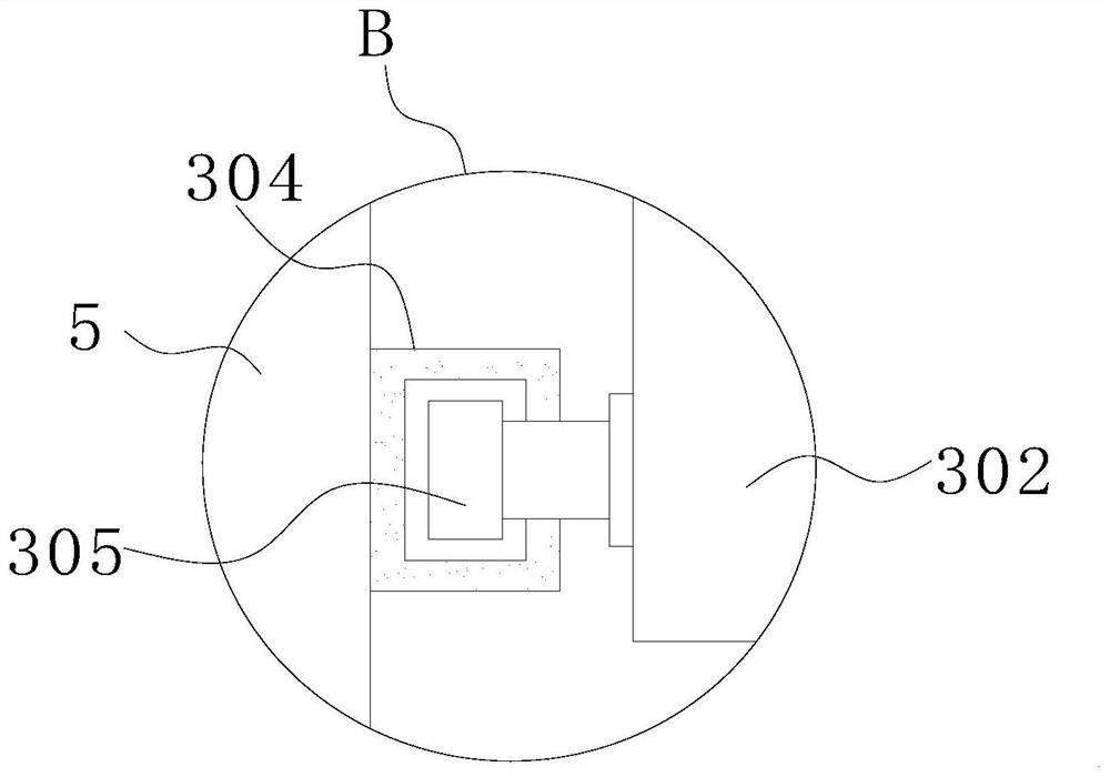
[0037]SeeFigure 1-10On the basis of the first example, the collecting mechanism 3 includes a handle 301, a water tank 302, a traveling wheel 303, a guide bracket 304, and a guide slider 305, and the water storage tank 302 is disposed below the operation plate 1, and the top of the water storage tank 302 is The opening is set, the support leg 5 is fixed to one side of the storage tank 302 fixedly mounted the guide bracket 304, and the guide bracket 304 slides to mounting the guide slider 305, and the side of the water tank 302 is fixedly connected to the guide slider 305, when the cutting work When the cutting fluid falls below the operating panel 1, the water storage tank 302 can perform a good collection of work, avoiding the water sprinkle, can improve the environment of the workplace, but also easy to recycle Homework, which is conducive to reducing staff's workers.
[0038]Further, the front side of the water storage tank 302 is fixedly mounted with the handle 301, and the bottom p...
Embodiment 3
[0040]SeeFigure 1-10On the basis of the first example, the lifting drive mechanism 2 includes a lifting slider 201, a guide rod 202, a disc 203, a mounting plate 204, a first gear 205, a second gear 206, a lifting rod 207, a first motor 208, and The support plate 209 is fixedly mounted on one side of the gantry 10, and the first motor 208 is fixed to the rear side of the mounting plate 204, and the disk 203 is fixedly mounted on the front side of the mounting plate 204, the output of the first motor 208 The shaft is fixed to the disc 203, and the disk 203 is fixedly mounted having a first gear 205, and the number of support plates 209 is two sets and fixed to one side of the gantry 10, and the two sets of support plates 209 are fixedly mounted. The guide rod 202, the lifting slider 201 is slidably disposed on the guide rod 202, the lifting slider 201 is fixedly connected to the connecting frame 9, and the lifting slider 201 is fixed from the side of the connecting frame 9 fixedly mo...
PUM
 Abstract
Description
Claims
Application Information
 - R&D
- Intellectual Property
- Life Sciences
- Materials
- Tech Scout
- Unparalleled Data Quality
- Higher Quality Content
- 60% Fewer Hallucinations
Browse by: Latest US Patents, China's latest patents, Technical Efficacy Thesaurus, Application Domain, Technology Topic, Popular Technical Reports.
© 2025 PatSnap. All rights reserved.Legal|Privacy policy|Modern Slavery Act Transparency Statement|Sitemap|About US| Contact US: help@patsnap.com