
Transformer oil level measuring device

A measuring device and transformer oil technology, applied in the direction of measuring device, lubrication indicator device, liquid/fluid solid measurement, etc., can solve the problems of inaccurate measurement, affecting measurement accuracy, error, etc., to save construction time, improve safety, The effect of improving detection accuracy

Active Publication Date: 2021-04-20
国网山西省电力公司朔州供电公司
View PDF5 Cites 0 Cited by
  • Summary
  • Abstract
  • Description
  • Claims
  • Application Information

AI Technical Summary

Problems solved by technology

However, the traditional measurement method based on the oil level gauge is not only inconvenient for digital acquisition, but also can cause inaccurate measurement due to blockage and other reasons.
[0004] There are various technical problems in the existing transformer oil level detection technology: (1) capacitive type: easy to be affected by pollution and produce errors; (2) resistive type: mechanical measurement, with large errors and hysteresis, and the sensor has long-term contact with the oil Contact, easy to be corroded, polluted, affecting measurement accuracy, and the fuel tank must be drilled during installation; (3) Flowmeter type: need to cut off the oil pipe, can not measure the amount of fuel, intelligent measurement of usage, inconvenient metering management; (4) Float Type: It can only be used for fuzzy indication of oil volume, not for oil volume measurement, the degree of oil pollution of film resistors, power supply voltage, mechanical structure, lubricity and other product reasons have a great impact on the long-term stability of the output value

Method used


Image

  • Transformer oil level measuring device
  • Transformer oil level measuring device
  • Transformer oil level measuring device

Examples


Embodiment 1

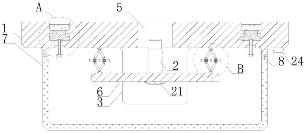
[0026] see Figure 1-4 , a transformer oil level measuring device, which is installed with the transformer oil tank and detects the oil level in the oil tank, including an installation base 1, a leveling mechanism, an ultrasonic probe 2, an electronic display screen 3, and a control unit 4;

[0027] The installation base 1 is fixedly installed on the bottom of the transformer oil tank. The ultrasonic probe 2 is installed together with the leveling mechanism on the installation base 1. The leveling mechanism adjusts the installation angle of the ultrasonic probe 2. The oil level in the tank is detected, and the installation base 1 is also equipped with an electronic display screen 3 and a control unit 4. The ultrasonic probe 2 is connected to the control unit 4 for signals. The control unit 4 is used to record the ultrasonic signal transmitted by the ultrasonic probe 2 to the transformer oil tank. Time and the time when the ultrasonic signal is reflected to the ultrasonic probe...

Embodiment 2

[0030] see Figure 1-4 Embodiment 1 is further described and supplemented in detail. In the present invention, a protective cover 7 is also provided, and an installation ring 8 is fixed on the edge of the installation base 1, and the protective cover 7 is screwed on the installation ring 8 and will be leveled. Mechanism, ultrasonic probe 2, electronic display 3, and control unit 4 are wrapped in it to protect the leveling mechanism, ultrasonic probe 2, electronic display 3, and control unit 4; the protective cover 7 is made of transparent engineering plastics to ensure that the protective cover 7 While improving the overall hardness, the oil level displayed on the electronic display screen 3 can be observed.

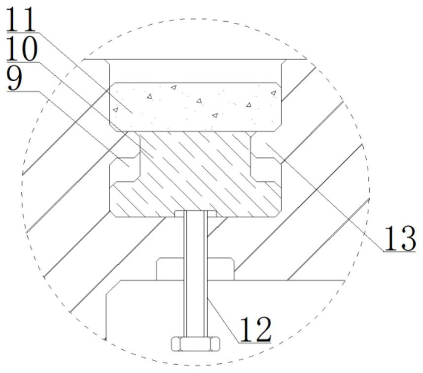
[0031] The edge position of the upper surface of the installation base 1 is provided with multiple sets of installation grooves 9, and a sliding installation seat 10 is nested and installed in the installation groove 9 in a relatively sliding manner, and a powerful magne...

Embodiment 3

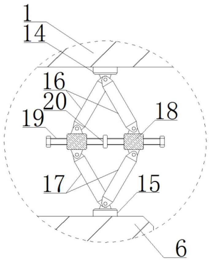
[0038] see Figure 1-4 , to explain the working principle of the present invention: when installing the present invention on the bottom of the transformer oil tank, first place the upper surface of the installation base 1 close to the transformer oil tank, and control the corresponding sliding mounting seat 10 and the strong force by twisting each group of driving screws 12 The magnet 11 moves upwards and is stably adsorbed on the bottom of the iron transformer oil tank; then, by rotating each group of driving screws 12 and continuously observing the indication status of the level meter 21, it is ensured that the installation substrate 6 is adjusted to a horizontal state, thereby ensuring that the ultrasonic probe 2 is vertically oriented The oil level in the transformer oil tank improves the accuracy of the ultrasonic probe 2 in detecting the oil level; finally, the protective cover 7 is installed on the mounting ring 8 to protect the leveling mechanism, the ultrasonic probe 2...


PUM


Abstract

The invention discloses a transformer oil level measuring device, which is characterized in that a mounting base is fixedly mounted at the bottom of a transformer oil tank, an ultrasonic probe and a leveling mechanism are mounted on the mounting base jointly in a matched manner, the leveling mechanism adjusts the mounting angle of the ultrasonic probe, and the ultrasonic probe detects the oil level in the transformer oil tank, an electronic display screen and a control unit are further installed on the mounting base, the ultrasonic probe is in signal connection with the control unit, and the control unit is used for recording the time when the ultrasonic probe transmits ultrasonic signals to the transformer oil tank and the time when the ultrasonic signals are reflected to the ultrasonic probe and calculating the oil liquid height, the control unit is in data connection with the electronic display screen and used for displaying the detected oil liquid height. The transformer oil level measuring device can efficiently perform disassembly and assembly work, improves the accuracy of oil level height detection, realizes remote monitoring of the oil level in each transformer oil tank, and improves the safety, reliability and sensitivity of products.

Description

technical field [0001] The invention relates to the technical field of transformer supporting equipment, in particular to a transformer oil level measuring device. Background technique [0002] The insulating oil inside the transformer has a much higher dielectric strength than air, has a good cooling effect, is a good arc-extinguishing medium, and at the same time plays a role in maintenance and anti-corrosion of insulating materials. It can be seen that insulating oil is very important for distribution transformers. [0003] Oil level is one of the important monitoring parameters of power transformers. It is of great significance to timely find out that the oil level is too low or too high and take corresponding measures to ensure the safe operation of power transformers. When the oil level is too high, it may cause the internal oil pressure of the transformer to increase, and also cause oil overflow. When the oil level is too low, the oil level will be further reduced w...

Claims


Application Information

Patent Timeline
Patent Type & Authority Applications(China)
IPC IPC(8): G01F23/296
Inventor 王鹏源刘义边小军李东明王铁铸
Owner 国网山西省电力公司朔州供电公司
Learn More