Outer rotor water cooling structure of permanent magnet synchronous hub motor

A hub motor and permanent magnet synchronous technology, applied in the direction of magnetic circuit shape/style/structure, cooling/ventilation device, magnetic circuit rotating parts, etc., can solve the problems affecting the safe and stable operation of the motor, the internal heat is difficult to discharge, and the permanent magnet is irreversible Demagnetization and other problems, to avoid irreversible demagnetization, simple manufacturing and assembly process, avoid the effect of magnetic performance decline

Inactive Publication Date: 2021-03-26
HARBIN UNIV OF SCI & TECH
View PDF7 Cites 2 Cited by
  • Summary
  • Abstract
  • Description
  • Claims
  • Application Information

AI Technical Summary

Problems solved by technology

However, because the hub motor drive system integrates the hub motor, deceleration mechanism, and brake in the wheel, the air circulation in the small space of the wheel is not smooth, and heat dissipation is difficult.
At the same time, the internal space of the hub motor is small, the loss density is relatively high, and the sealing is required to be high. It is difficult to discharge the internal heat during the operation of the motor, which will cause the motor to overheat, the temperature of the permanent magnet will increase, the magnetic performance will decrease, and even the permanent magnet will be irreversible. Demagnetization seriously affects the safe and stable operation of the motor, so designing an efficient permanent magnet cooling structure is of great significance to prolong the service life of the hub motor and improve the performance of the vehicle

Method used


Image

  • Outer rotor water cooling structure of permanent magnet synchronous hub motor
  • Outer rotor water cooling structure of permanent magnet synchronous hub motor
  • Outer rotor water cooling structure of permanent magnet synchronous hub motor

Examples


Embodiment Construction

[0017] The specific embodiments of the present invention will be further described below in conjunction with the accompanying drawings.

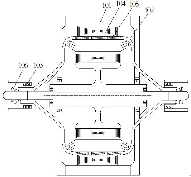
[0018] Such as figure 1 As shown, an outer rotor water-cooled cooling structure of a permanent magnet synchronous hub motor includes an outer rotor permanent magnet synchronous hub motor 101, an outer rotor water cooling pipe 102, a waterproof bearing 103 and an axial flow impeller 106; the outer rotor water cooling pipe 102 is welded between the inner ring 103 of the waterproof bearing and the outer surface of the shaft of the axial flow impeller 106, passes through the inside of the hub motor 101, and is in close contact with the periphery of the permanent magnet 105 and the inner wall of the rotor core 104. Seen from the left end, when the outer rotor hub motor 101 rotates clockwise, it drives the outer rotor water cooling pipe 102 and the axial flow impeller 106 to rotate, and the cooling water passes through the axial flow impeller 106 ...


PUM


Abstract

The invention relates to the technical field of hub motors, in particular to an outer rotor water cooling structure of a permanent magnet synchronous hub motor, which comprises an outer rotor permanent magnet synchronous hub motor, an outer rotor waterway cooling pipe, a waterproof bearing and an axial flow impeller, the two ends of the outer rotor waterway cooling pipe are welded between the inner ring of the waterproof bearing and the surface of an axial-flow impeller shaft and are tightly attached to the periphery of motor permanent magnets and the inner wall of a rotor core through end covers. When the hub motor rotates, the outer rotor waterway cooling pipe and the axial flow impeller are driven to rotate, and cooling water enters the outer rotor waterway cooling pipe through the axial flow impeller to cool the permanent magnets. A rotor adopts water internal cooling, the temperature rise of the permanent magnets is low, the reduction of magnetic performance and irreversible demagnetization of the permanent magnets due to over-high temperature are avoided, and the motor is reliable in operation. The permanent magnet adopts an axial segmented structure, and omega-shaped coolingwater pipes are arranged between every two adjacent permanent magnets, so that waterways can be in full contact with the permanent magnets and the inner wall of the rotor, and the heat dissipation isimproved; the permanent magnet segmented structure can significantly reduce the eddy current loss of the permanent magnets and reduce heat generation.

Description

technical field [0001] The invention relates to the technical field of hub motors, in particular to a water-cooling structure for an outer rotor of a permanent magnet synchronous hub motor. Background technique [0002] Due to energy shortage and environmental pollution, energy-saving and environmentally friendly new energy vehicles have become the development trend of the automotive industry. Due to the combination of in-wheel motors and power electronic devices, it has many advantages such as high integration, high transmission efficiency, simplified chassis structure, flexible layout, four-wheel independent control, and space saving in the car. However, since the in-wheel motor drive system integrates the in-wheel motor, deceleration mechanism, and brake in the wheel, the air circulation in the narrow space of the wheel is not smooth and heat dissipation is difficult. At the same time, the internal space of the hub motor is small, the loss density is relatively high, and...

Claims


Application Information

Patent Timeline
Patent Type & Authority Applications(China)
IPC IPC(8): H02K9/19H02K1/27H02K1/32
CPCH02K9/19H02K1/2786H02K1/32
Inventor 戈宝军程艳林燕跃松
Owner HARBIN UNIV OF SCI & TECH
Why Eureka
Try Eureka