
Shockproof mechanical drilling device with scrap cleaning and recycling function

A mechanical drilling and functional technology, applied in the direction of feeding device, boring/drilling, drilling/drilling equipment, etc., can solve the problems of affecting the drilling of objects, reducing the service life of machinery, and excessive heat generation, etc., to reduce The effect of not being able to drill normally, improving work efficiency, and increasing versatility

Inactive Publication Date: 2021-03-05
叶红飞
View PDF2 Cites 1 Cited by
  • Summary
  • Abstract
  • Description
  • Claims
  • Application Information

AI Technical Summary

Problems solved by technology

[0004] The object of the present invention is to provide a kind of anti-vibration mechanical drilling device with waste cleaning and recovery function, in order to solve the problem that the existing drilling machine proposed in the above-mentioned background technology is in use, because most of the existing drilling machines do not The shock absorbing mechanism transmits the vibration during operation to the machine, causing the internal structure of the machine to be vibrated, which is prone to structural cracking and reduces the service life of the machine. During the drilling work of the machine, waste chips will be generated. If the waste is not removed in time The waste will cover a large area on the workbench, and some waste may affect the normal drilling work. In addition, when the drill is drilling an object, the drill itself will heat up too quickly, resulting in a decrease in the toughness of the drill. Thus affecting the drilling of the object, resulting in the problem that the subsequent drilling work cannot be carried out normally

Method used


Image

  • Shockproof mechanical drilling device with scrap cleaning and recycling function
  • Shockproof mechanical drilling device with scrap cleaning and recycling function
  • Shockproof mechanical drilling device with scrap cleaning and recycling function

Examples


Embodiment 1

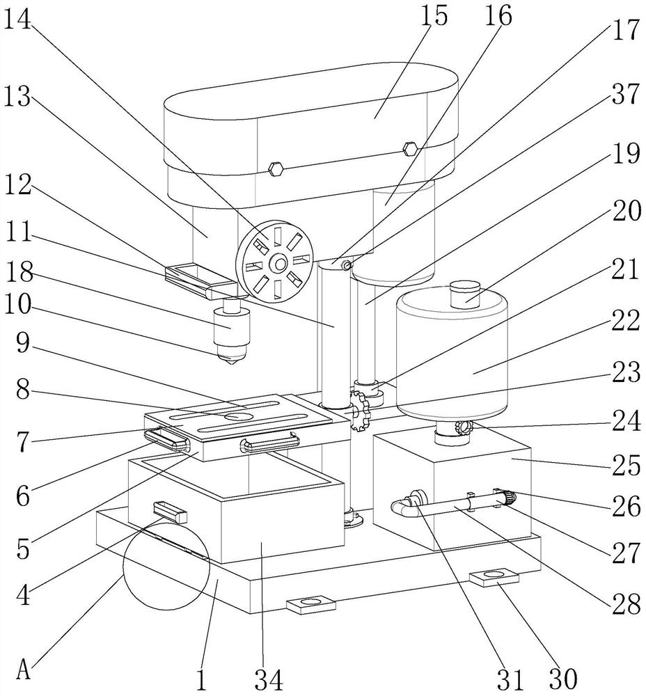
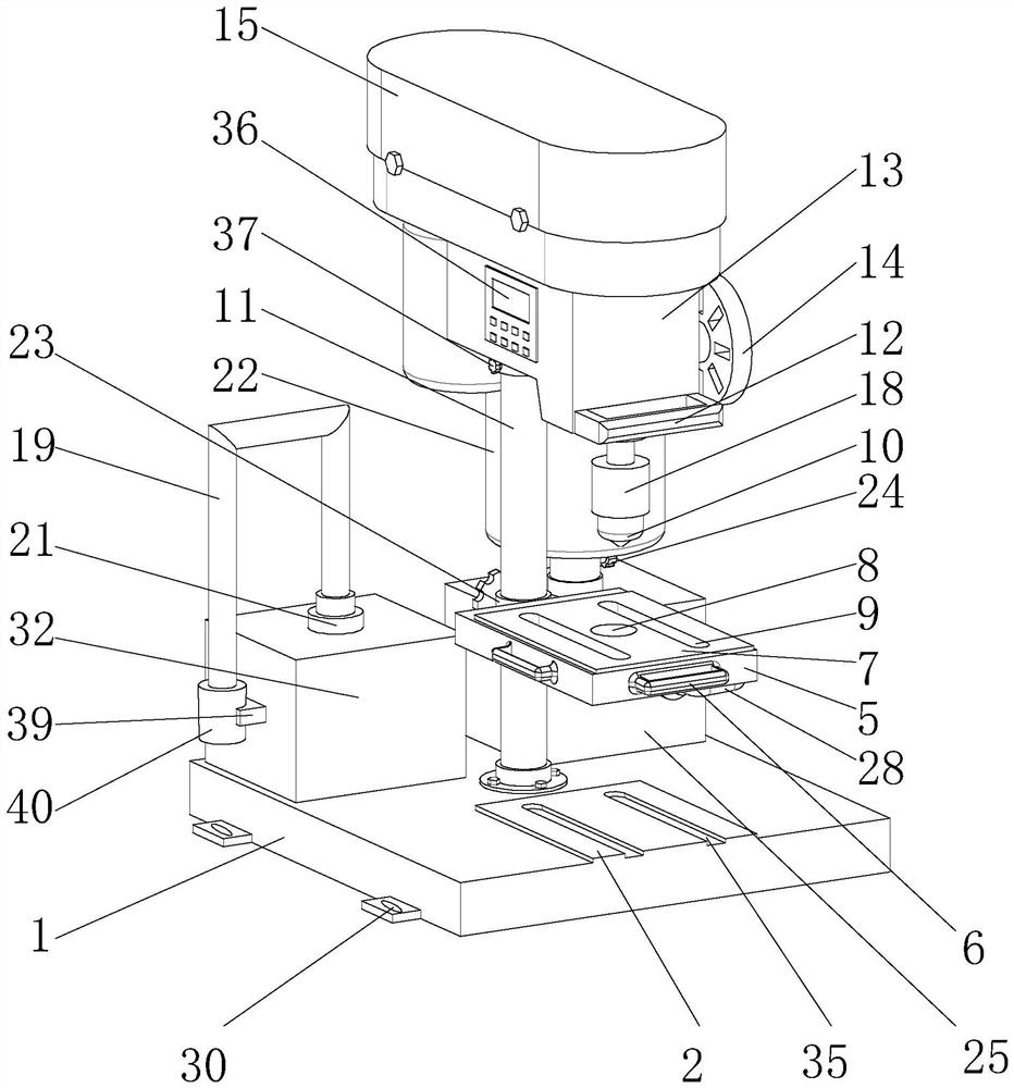
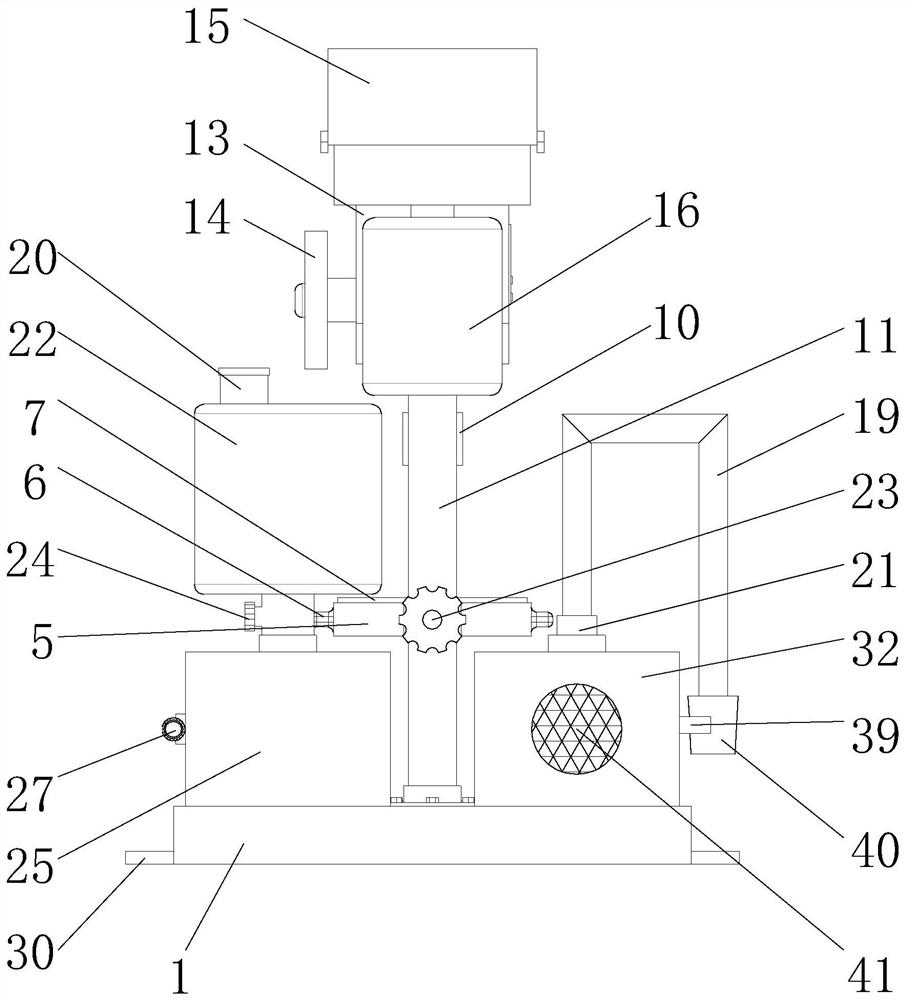
[0030] see Figure 1-8 , the present invention provides a technical solution: including a base 1, a first workbench 2 is fixedly installed on the top of the base 1, a recovery box 34 is movably installed on the top of the first workbench 2, and a pole frame is fixedly installed on the top of the base 1 11. The top of the rod frame 11 is movably installed with a control case 13, the top of the control case 13 is fixed with an organic case 15, the top of the base 1 is fixed with a water pump casing 25, and the front of the water pump casing 25 is connected with a second connecting pipe 31 The end of the second connecting pipe 31 far away from the water pump housing 25 is connected with a soft water pipe 28, and the end of the soft water pipe 28 away from the second connecting pipe 31 is fixedly installed with a nozzle 27, and the top of the water pump housing 25 is connected with a water bucket 22, and the top of the base 1 A drying device 32 is fixedly installed, and the top of...

Embodiment 2

[0033] Such as Figure 1-8 As shown, on the basis of Embodiment 1, the present invention provides a technical solution: the front of the recovery box 34 is fixedly equipped with a push-pull handle 4, the inside of the first workbench 2 is provided with a chute 35, and the bottom of the recovery box 34 is fixed A slide block 3 is installed, and the slide block 3 is slidably installed in the inside of the chute 35. An adjustment ring 23 is installed on the outside of the pole frame 11, and a base 5 is fixedly installed on the end of the adjustment ring 23 away from the pole frame 11. The front and both sides of 5 are all fixedly installed with first handle 6, and the top of base 5 is fixedly installed with second workbench 7, and the inside of base 5 and second workbench 7 is provided with drill hole 8, and base 5 is connected with the second workbench 7. The inside of the second workbench 7 is provided with a card slot 9 .

[0034] In this embodiment, sliding the slider 3 at t...

Embodiment 3

[0036] Such as Figure 1-8 As shown, on the basis of Embodiment 1 and Embodiment 2, the present invention provides a technical solution: the bottom of the control shell 13 is fixedly installed with a rotating device 17, and the rotating device 17 is sleeved on the outside of the top of the pole frame 11, and the rotating device 17 is installed with fastening bolts 37, the front of the control shell 13 is fixedly equipped with a second handle 12, one side of the control shell 13 is fixedly equipped with a control panel 14, and the side of the control shell 13 away from the control panel 14 is fixedly installed with a Control panel 36, hydraulic cylinder 18 is installed on the inside of control shell 13 bottom, the bottom of hydraulic cylinder 18 is fixedly equipped with deep hole drill bit 10, the bottom of casing 15 is fixedly installed with rotating motor 16, and the top of hydraulic cylinder 18 is fixedly connected with Shaft 43, a second gear 42 is fixedly installed on the ...


PUM


Abstract

The invention discloses a shockproof mechanical drilling device with a scrap cleaning and recycling function. The shockproof mechanical drilling device with the scrap cleaning and recycling function comprises a base, wherein a first workbench is fixedly installed at the top of the base; a recycling box is fixedly installed at the top of the first workbench; a supporting rod frame is fixedly installed at the top of the base; a control shell is fixedly installed at the top of the supporting rod frame; a machine shell is fixedly installed at the top of the control shell; a water pump shell is fixedly installed at the top of the base; a drying device is fixedly installed at the top of the base; and the top of the drying device communicates with a first connecting pipe. A recovery box is arranged to slide into sliding grooves through bottom sliding blocks, so that drilling scraps falling from a second workbench can be received, the effect of recovering the scraps is achieved, the situationthat the scraps and garbage fall around and are difficult to clean is prevented, the influence of scraps covering the second workbench on the drilling of an object is avoided, the object drilling effect of a drill bit is improved to the maximum extent, and the problem that normal drilling cannot be conducted in the drilling work is effectively solved.

Description

technical field [0001] The invention belongs to the technical field of mechanical devices, and in particular relates to an anti-vibration mechanical drilling device with the function of cleaning and recovering waste. Background technique [0002] Drilling machine refers to the general name of machinery and equipment that leaves cylindrical holes or holes on the target by means of rotary cutting or rotary extrusion with a tool that is harder and sharper than the target. Machines, drilling machines, through-hole machines, etc., achieve the desired effect by drilling precision parts. Drilling machines include semi-automatic drilling machines and fully automatic drilling machines. With the increase in human resource costs, most enterprises Both consider fully automatic drilling machines as the development direction. With the development of the times and the improvement of the drilling technology of automatic drilling machines, fully automatic drilling machines are used to drill ...

Claims


Application Information

Patent Timeline
Patent Type & Authority Applications(China)
IPC IPC(8): B23B39/00B23B47/22B23Q11/00B23Q11/10
CPCB23B39/00B23Q5/26B23Q11/0032B23Q11/0042B23Q11/10
Inventor 叶红飞
Owner 叶红飞
Learn More