
Guide sleeve of hydraulic oil cylinder

A technology of hydraulic oil cylinder and guide sleeve, applied in the field of hydraulic oil cylinder, can solve the problems of increasing wear consumption, wear, hydraulic oil leakage, etc., and achieve the effects of increasing service life, reducing wear and reducing impact

Pending Publication Date: 2022-01-21
黄玉央
View PDF0 Cites 0 Cited by
  • Summary
  • Abstract
  • Description
  • Claims
  • Application Information

AI Technical Summary

Problems solved by technology

[0005] The specific problem to be solved by the present invention is: in the mutual friction between the guide sleeve and the piston rod, the hydraulic oil in the oil cylinder enters the friction position for lubrication is less, and the dry friction increases the wear consumption, while the guide sleeve and the piston rod are connected. The wear of the position will cause damage to the sealing system of the oil cylinder. At this time, the entire guide sleeve needs to be replaced, resulting in a waste of resources. During the working process of the hydraulic cylinder, the impact and wear of the piston on the guide sleeve body will cause wear at the end of the guide sleeve body. In turn, the end seal will fail, resulting in hydraulic oil leakage and shortening the service life of the guide sleeve

Method used


Image

  • Guide sleeve of hydraulic oil cylinder
  • Guide sleeve of hydraulic oil cylinder
  • Guide sleeve of hydraulic oil cylinder

Examples


Embodiment Construction

[0020] The technical solutions in the embodiments of the present invention will be clearly and completely described below in conjunction with the accompanying drawings in the embodiments of the present invention. Obviously, the described embodiments are only some of the embodiments of the present invention, not all of them. Based on The embodiments of the present invention and all other embodiments obtained by persons of ordinary skill in the art without making creative efforts belong to the protection scope of the present invention.

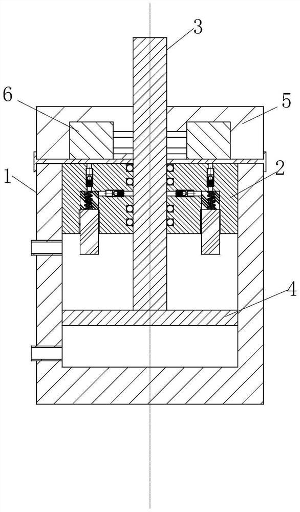
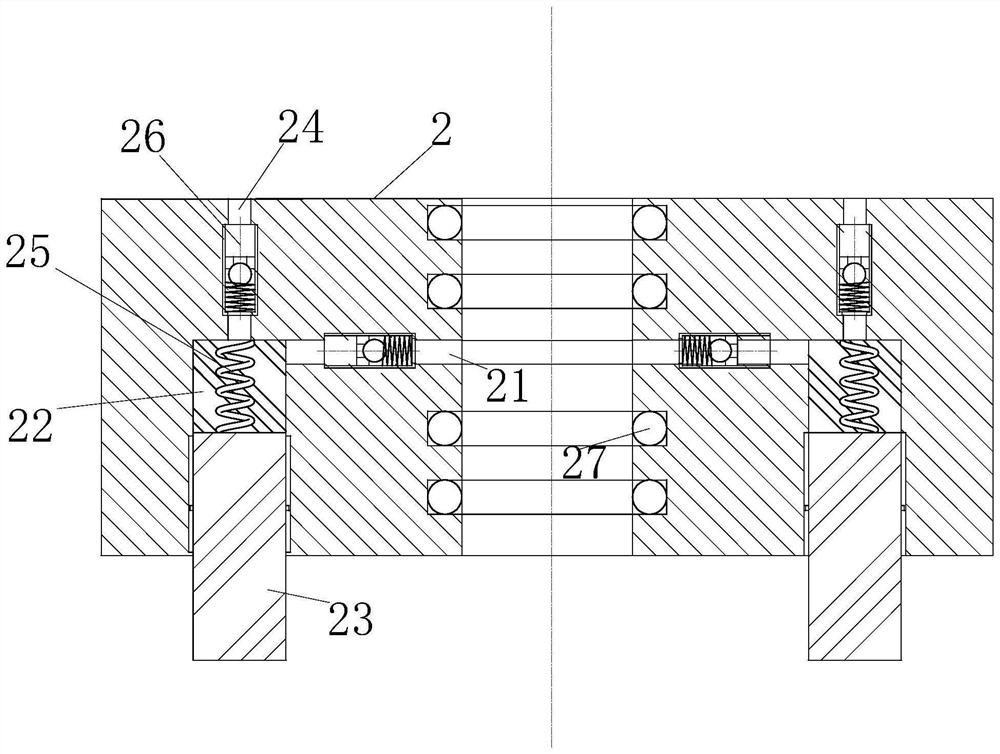
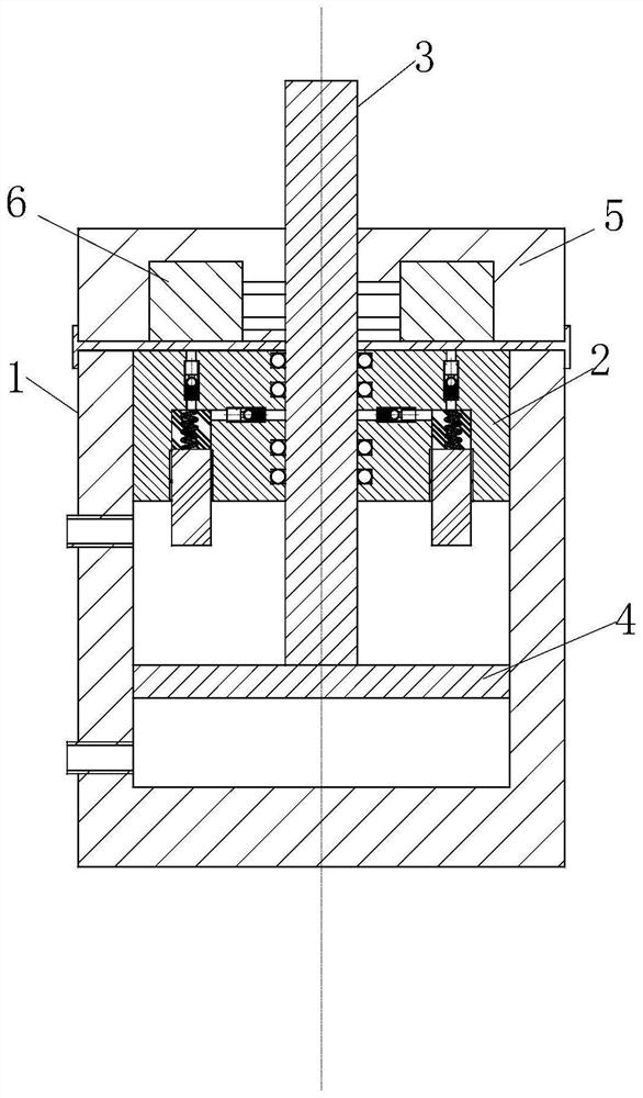
[0021] The present invention provides a guide sleeve of a hydraulic cylinder, comprising a cylinder body 1, a guide sleeve 2, a through hole 21, a sponge 22, an annular ring 23, a piston rod 3 and a piston 4, and the top of the inner wall of the cylinder body 1 is sealed and slidably connected The guide sleeve 2, the inner wall of the cylinder body 1 is sealed and slidably connected to the piston 4, the piston rod 3 is fixedly connected above the...


PUM


Abstract

The invention belongs to the technical field of hydraulic oil cylinders and particularly relates to a guide sleeve of a hydraulic oil cylinder. The guide sleeve is characterized in that springs and sponges are arranged in a cavity; an annular ring is made of an elastic material, and can play a buffering role in the sponge and spring squeezing process, thereby reducing the impact of a piston on the guide sleeve, reducing the abrasion of a piston rod and the guide sleeve, and prolonging the service life; through the formation of a No.1 through hole, squeezed oil can enter the No.1 through hole and flow to the piston rod in the sponge squeezing process, so as to lubricate the piston rod; through the arrangement of oil suction pumps, the oil which is brought out by the piston rod from the interior of a cylinder body can be sucked and can flow through No.2 through holes into the cavity, thereby achieving the recycling effect; and grooves are formed in the inner wall of the guide sleeve in a spacing manner, and steel balls are arranged in the grooves and are in rolling connection with the piston rod, so that the friction between the piston rod and the guide sleeve can be reduced, the abrasion of the piston rod and the guide sleeve can be further reduced, and the service life of the hydraulic oil cylinder can be prolonged.

Description

technical field [0001] The invention belongs to the technical field of hydraulic cylinders, in particular to a guide sleeve of hydraulic cylinders. Background technique [0002] The hydraulic cylinder is a hydraulic actuator that converts hydraulic energy into mechanical energy and performs linear reciprocating motion (or swinging motion). It has a simple structure and reliable operation. When it is used to realize reciprocating motion, the deceleration device can be eliminated and there is no transmission gap. , The movement is stable, so it is widely used in various mechanical hydraulic systems. The guide sleeve of the hydraulic cylinder is installed at the front end of the cylinder barrel to guide and seal the piston rod. [0003] In the prior art, in order to ensure the sealing between the guide sleeve and the piston rod, usually the cooperation between the two is relatively tight. During the mutual friction between the guide sleeve and the piston rod, the hydraulic oil ...

Claims


Application Information

Patent Timeline
Patent Type & Authority Applications(China)
IPC IPC(8): F15B15/17F15B15/20F15B15/22F16C29/04F16C33/66
CPCF15B15/17F15B15/1423F15B15/226F16C29/04F16C33/6659F16C33/6681
Inventor 黄玉央许涛
Owner 黄玉央
Learn More