
Speed change pressure flow field control method applicable to intermittent transonic speed wind tunnel

A control method and transonic technology, which are applied in electric fluid pressure control, testing of machine/structural components, measuring devices, etc., can solve the problems of large model shock, model shock, large overshoot, etc., and achieve rapid pressure rise. Stable and reliable test effect, the effect of reducing impact

Inactive Publication Date: 2013-05-29
INST OF HIGH SPEED AERODYNAMICS OF CHINA AERODYNAMICS RES & DEV CENT
View PDF2 Cites 56 Cited by
  • Summary
  • Abstract
  • Description
  • Claims
  • Application Information

AI Technical Summary

Problems solved by technology

[0010] 1. During the start-up and pressurization process of the wind tunnel, the time-optimized control strategy is mainly adopted, resulting in a large overshoot of the total pressure and Mach number, which has a large impact on the model and cannot meet the needs of the flutter test;
[0011] 2. In the stable stage of the flow field, the wind tunnel does not have the function of stepped variable speed pressure;
[0012] 3. During the shutdown stage of the wind tunnel, the wind tunnel flow field is out of control, which will have a greater impact on the model
[0013] Therefore, this traditional flow field control method cannot meet the needs of the flutter test, so it is necessary to redevelop a new flow field control method to meet the test requirements

Method used


Image

  • Speed change pressure flow field control method applicable to intermittent transonic speed wind tunnel
  • Speed change pressure flow field control method applicable to intermittent transonic speed wind tunnel
  • Speed change pressure flow field control method applicable to intermittent transonic speed wind tunnel

Examples


Embodiment

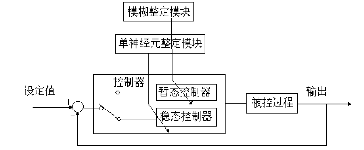
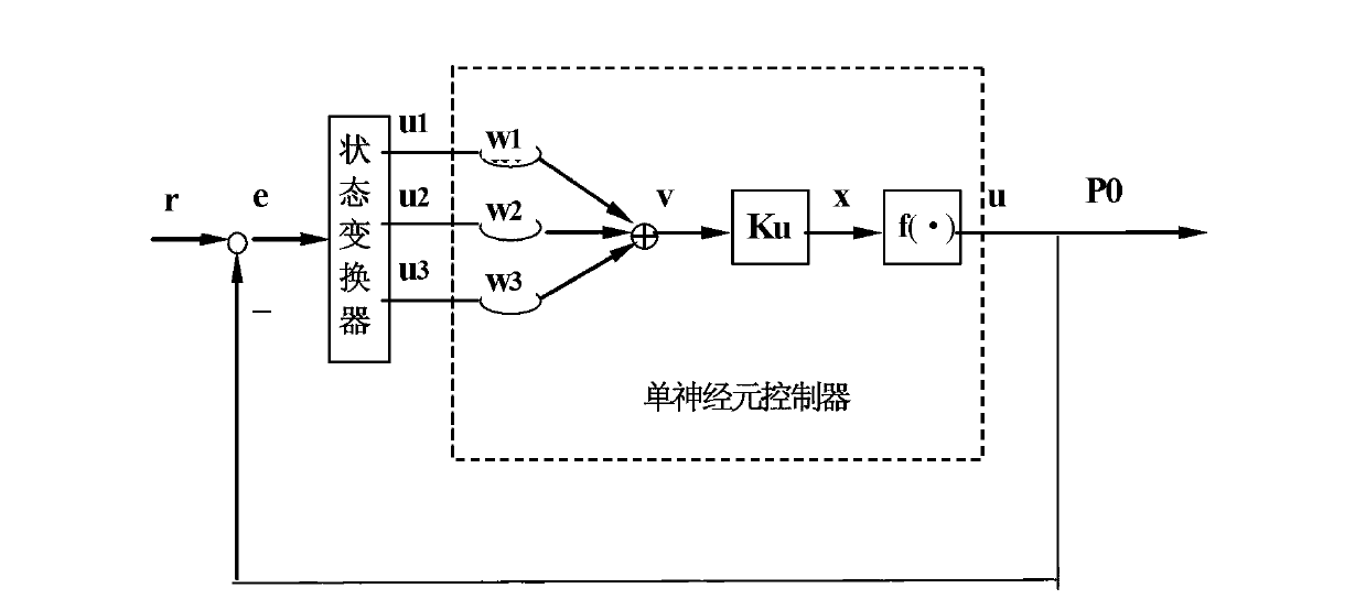
[0037] The wind tunnel control system mainly includes the main pressure regulating valve control system, the main exhaust valve control system, the grid finger control system, and the chamber flow valve control system. Among them, the main pressure regulating valve control system is mainly responsible for controlling the total pressure of the wind tunnel and the pressure of the main ejector; the main exhaust valve control system is mainly responsible for controlling the total pressure of the wind tunnel; Mach number (when 0.3<Ma<0.95, the grid finger is used to adjust the Mach number; when 0.95<Ma<1.05, the grid finger and the chamber flow valve are used to adjust the Mach number; when 1.05<Ma<1.2, the chamber flow valve is used adjust the Mach number).

[0038] The main parameters involved in the wind tunnel include: the total pressure of the wind tunnel P 0 , wind tunnel static pressure P ct , main ejector pressure P zy , Mach number Ma and speed pressure q. Among them, ...


PUM


Abstract

The invention provides a speed change pressure flow field control method applicable to an intermittent transonic speed wind tunnel, and relates to the technical field of aerospace industry wind tunnel tests. The speed change pressure flow field control method applicable to the intermittent transonic speed wind tunnel solves the problem that a traditional flow field control method can not meet the requirements of flutter tests. The technical scheme includes: enabling total pressure and main ejector pressure to rise to first stage set value in a given rate after a wind tunnel starts ramming; controlling a mach number to reach set target value in a flow field regulating procedure; controlling a main pressure regulating valve and a main air discharge valve so as to enable the total pressure of the wind tunnel and the main ejector pressure to reach respective target value in a change total pressure regulating procedure; and controlling the current main ejector pressure to gradually drop to set shutdown main ejector pressure and controlling the current wind tunnel total pressure to gradually drop to set wind tunnel total pressure value when the wind tunnel is shut down. The speed change pressure flow field control method applicable to the intermittent transonic speed wind tunnel can meet the requirements of the flutter tests for intermittent transonic speed wind tunnel flow field control, has rapid, accurate and reliable test effects, and furthermore is high in total pressure control and mach number control accuracy.

Description

technical field [0001] The invention relates to the technical field of wind tunnel tests in the aerospace industry, in particular to a variable-speed pressure flow field control method suitable for a transient transonic wind tunnel. Background technique [0002] Flutter is a destructive vibration that occurs on an aircraft. Once the flight pressure exceeds a critical value, the amplitude increases rapidly. It is a self-excited vibration under the action of aerodynamic force, elastic force and inertial force, and is the result of absorbing energy from the airflow. Due to the harmfulness of flutter, flutter is absolutely not allowed within the flight envelope of the aircraft. The purpose of the aircraft flutter test is: (1) select the aircraft structure scheme, and study the influence of structural parameters on the flutter characteristics; (2) check the flutter characteristics of the designed aircraft; (3) verify the theoretical calculation method. In order to evaluate the ...

Claims


Application Information

Patent Timeline
Patent Type & Authority Applications(China)
IPC IPC(8): G05D16/20G01M9/04
Inventor 杜宁芮伟路波易凡余立罗建国杨兴华秦建华郁文山郭洪涛金志伟龙秀虹马永一苏北辰蒋婧妍
Owner INST OF HIGH SPEED AERODYNAMICS OF CHINA AERODYNAMICS RES & DEV CENT
Learn More