Method for eliminating tiny deformation in batch forming of slender thin-wall crack line sources

A line source and crack technology, applied in the field of CNC precision machining and manufacturing, can solve the problems of delaying the alignment time of the clamping, reducing the machining quality of the line source, inconsistency between the center line of the waveguide and the machining reference, etc., so as to eliminate subtle differences and improve Processing quality and processing efficiency, avoiding the effect of excessive clamping force

Inactive Publication Date: 2021-03-02
THE 724TH RES INST OF CHINA SHIPBUILDING IND
View PDF8 Cites 1 Cited by
  • Summary
  • Abstract
  • Description
  • Claims
  • Application Information

AI Technical Summary

Problems solved by technology

[0002] Due to the influence of comprehensive factors such as waveguide cross-sectional size deviation, straightness, twist, and thin-walled waveguides due to poor rigidity and variability in the structural characteristics of slight deformation in the production process, the difference between each waveguide is superimposed. Even the different positions of the same waveguide have slight differences. Many comprehensive subtle differences will seriously delay the clamping and alignment time in the processing of slender and thin-walled crack line sources, especially in batch molding, resulting in the center line of the waveguide and the Inconsistent processing standards, reducing the quality of line source processing

Method used


Image

  • Method for eliminating tiny deformation in batch forming of slender thin-wall crack line sources
  • Method for eliminating tiny deformation in batch forming of slender thin-wall crack line sources
  • Method for eliminating tiny deformation in batch forming of slender thin-wall crack line sources

Examples


Embodiment Construction

[0020] The present invention will be further explained with reference to the drawings and embodiments.

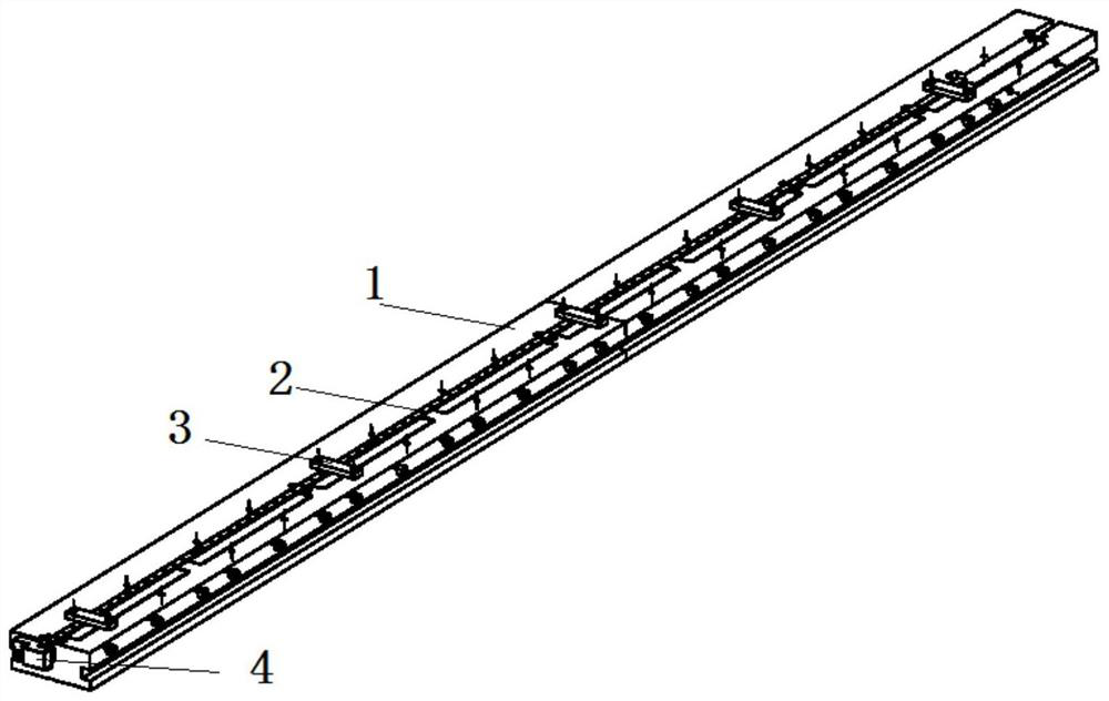
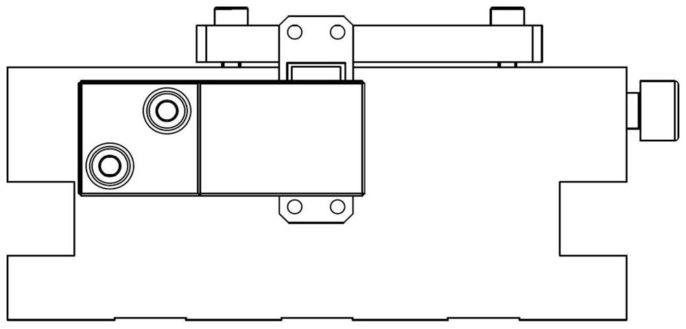
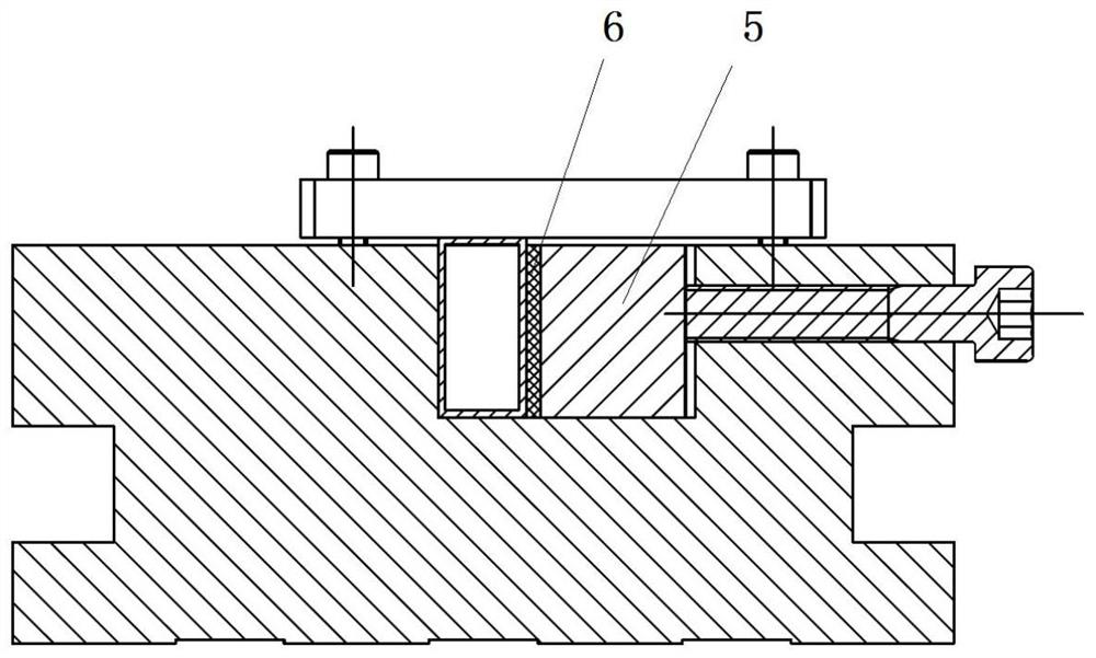
[0021] Taking the milling 3A21 crack line source with a wall thickness of 1mm and external dimensions of 12.16mm×24.86mm×2098mm as an example, the method of the present invention for eliminating the subtle difference factors in the batch forming of slender and thin-walled crack line sources includes 55mm×130mm×2080mm The special fixture is made into a whole or divided into two parts according to the specific conditions during processing. The surface is provided with a step groove for detecting the coordinates of the centerline of the line source; the 2mm thick elastic liner can be made of polytetrafluoroethylene, and placed between the side pressure plate and the Avoid rigid contact between cracked wire sources and realize flexible clamping; 15-20mm thick, 250×23.8-24.3mm aluminum side pressure plate is used to fasten the side of the wire source and reduce the clamping force...


PUM

PropertyMeasurementUnit
Linearityaaaaaaaaaa

Abstract

The invention belongs to the technical field of numerical control precision machining and manufacturing, and provides a method for eliminating tiny deformation in batch forming of slender thin-wall crack line sources. According to the method, the sizes and the positions of the line sources are measured by designing a special clamp and utilizing a machine tool probe; then, the clamping pretightening force is judged and finely adjusted; and the values about the deviations between the two-end positions of each crack on a waveguide top surface and datum points are collected point by point as wellas recorded in a machine tool macroprogram for being called by a machining program so as to compensate for the tiny deformation. Consequently, the influence of such comprehensive subtle factors as thewaveguide tube section size deviation, the straightness, the twisting degree and the tiny deformation generated in the production process as well as the difference among waveguide tubes on the precision of the crack line sources can be creatively eliminated; the coincidence between the process datum and the design datum can be guaranteed; the deformation, caused by the clamping, of thin-wall waveguide tube cavities can be reduced; and the machining precision can be improved.

Description

technical field [0001] The invention relates to the technical field of numerical control precision machining and manufacturing. Background technique [0002] Due to the influence of comprehensive factors such as waveguide cross-sectional size deviation, straightness, twist, and thin-walled waveguides due to poor rigidity and variability in the structural characteristics of slight deformation in the production process, the difference between each waveguide is superimposed. Even the different positions of the same waveguide have slight differences. Many comprehensive subtle differences will seriously delay the clamping and alignment time in the processing of slender and thin-walled crack line sources, especially in batch molding, resulting in the center line of the waveguide and the Inconsistent processing standards reduce the quality of line source processing. Contents of the invention [0003] In order to ensure processing quality, improve production efficiency, realize f...

Claims


Application Information

Patent Timeline
IPC IPC(8): B23P15/00B23Q3/06
CPCB23P15/00B23Q3/064
Inventor 张满意陈杨
Owner THE 724TH RES INST OF CHINA SHIPBUILDING IND
Why Eureka
Try Eureka