Method and device for synthesizing phthalimide multifunctional organic light-emitting material
A technology of phthalimide and luminescent materials, applied in luminescent materials, organic chemistry, cleaning methods and appliances, etc., can solve problems affecting product quality, incomplete reaction, and carbonization of products, etc., to reduce cleaning Effects of difficulty, increased reaction rate, and energy saving
- Summary
- Abstract
- Description
- Claims
- Application Information
AI Technical Summary
Problems solved by technology
Method used
Image
Examples
Embodiment 1
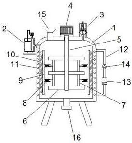
[0049] like figure 1 , 4 As shown, a synthesis device of a phthalimide multifunctional organic light-emitting material; including a tank body 1; the top of the tank body 1 is provided with a first motor 4, and the output shaft of the first motor 4 is connected to A stirring shaft 5, the stirring shaft 5 extends through the top wall of the tank body 1 to the inside of the tank body 1, the stirring shaft 5 is provided with a plurality of stirring teeth 6, and a fixed rod 7 is connected between the plurality of stirring teeth 6, so An adjustment mechanism 8 is vertically connected to the fixed rod 7, the adjustment mechanism 8 is connected to the scraper 9, and the bristles 10 are arranged on the hanging plate; the bristles 10 are closely arranged with the inner wall of the tank body 1; the first motor 4 One side of the tank body is provided with a feeding port 15, and the bottom of the tank body 1 is provided with a feeding port 16;
[0050] The position of the side wall of th...
Embodiment 2
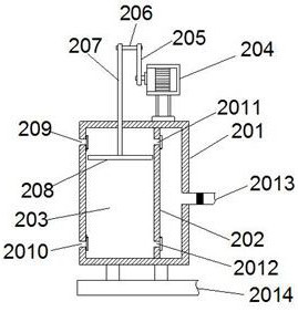
[0054] On the basis of Example 1, as figure 2 As shown, the pressurization mechanism 2 includes a box body 201, the bottom of the box body 201 is connected with a fixing seat 2014, and the box body 201 is connected with the tank body 1 through the fixing seat 2014; the inside of the box body 201 is provided with a partition 202, so The partition plate 202 and the box body 201 form a booster chamber 203; the top of the box body 201 is provided with a second motor 204, the output shaft of the second motor 204 is connected with a cam 205, and the cam 205 is connected with a connecting rod 206, the other end of the connecting rod 206 is connected with a moving rod 207; the moving rod 207 runs through the wall of the box body 201, and forms a sliding connection with the box body 201; the other end of the moving rod 207 extends into the booster chamber 203 , the other end of the moving rod 207 is connected with a sliding plate 208 , and the sliding plate 208 is airtightly and slida...
Embodiment 3
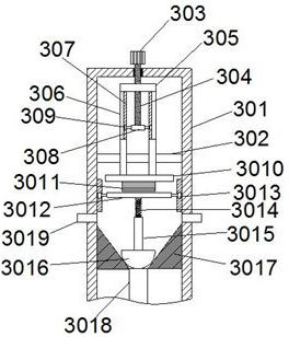
[0059] like image 3 As shown, on the basis of Embodiment 1, the constant pressure mechanism 3 includes a housing 301, and the bottom of the housing 301 is connected with an air outlet 3018, and the air outlet 3018 communicates with the tank body 1; the air outlet 3018 A sealing ring 3017 is arranged above, and the section of the sealing ring 3017 is a "V"-shaped structure; a sealing block 3016 is arranged inside the sealing ring 3017, and the sealing block 3016 has a hemispherical structure, and the sealing block 3016 and the air outlet 3018 is correspondingly tightly connected; the other end of the housing 301 close to the sealing ring 3017 is provided with an exhaust hole 3019, the other end of the sealing block 3016 is connected with a guide rod 3015, and the other end of the guide rod 3015 is connected with a first The spring 3014, the other end of the first spring 3014 is connected with the moving plate 3012.
[0060]The two ends of the moving plate 3012 are connected w...
PUM
 Abstract
Description
Claims
Application Information
 - R&D
- Intellectual Property
- Life Sciences
- Materials
- Tech Scout
- Unparalleled Data Quality
- Higher Quality Content
- 60% Fewer Hallucinations
Browse by: Latest US Patents, China's latest patents, Technical Efficacy Thesaurus, Application Domain, Technology Topic, Popular Technical Reports.
© 2025 PatSnap. All rights reserved.Legal|Privacy policy|Modern Slavery Act Transparency Statement|Sitemap|About US| Contact US: help@patsnap.com


