Industrial kiln waste heat recovery device

A waste heat recovery device and waste heat recovery technology, applied in furnaces, waste heat treatment, furnace components, etc., can solve problems such as increased production costs, environmental pollution, waste of resources, etc., and achieve reduced pollution, high heat recovery efficiency, and improved thermal efficiency. Effect

Pending Publication Date: 2021-02-09
杭州瑞思新材料有限公司
View PDF0 Cites 2 Cited by
  • Summary
  • Abstract
  • Description
  • Claims
  • Application Information

AI Technical Summary

Problems solved by technology

[0004] The internal heating temperature of the kiln is generally more than 1,000 degrees, and the exhaust gas contains high waste heat, which is generally discharged directly into the air, which wastes a lot of resources and increases production costs.
In addition, kiln exhaust gas often contains a large amount of smoke and dust. If these exhaust gases are directly discharged into the air, it is easy to cause pollution to the environment.

Method used


Image

  • Industrial kiln waste heat recovery device
  • Industrial kiln waste heat recovery device
  • Industrial kiln waste heat recovery device

Examples


Embodiment 1

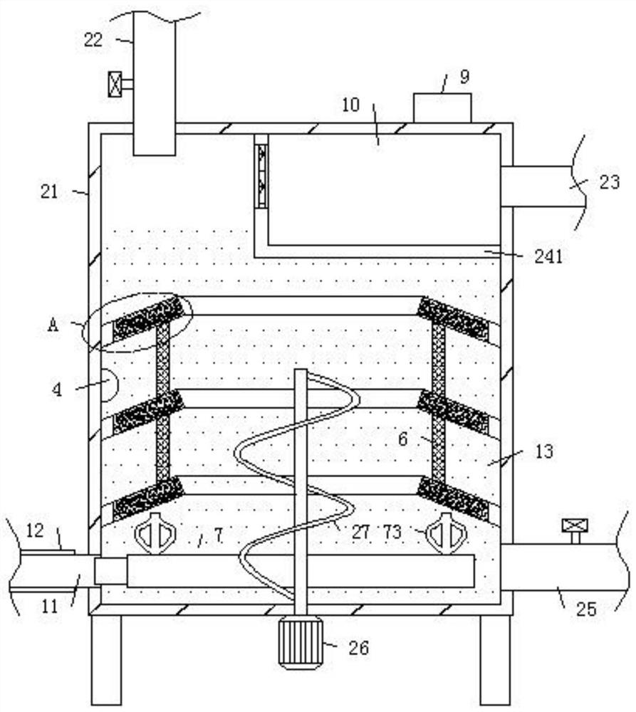
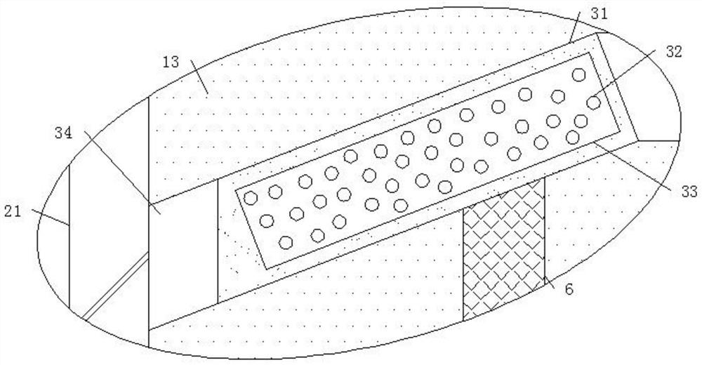
[0041] see Figure 1-7 An industrial kiln 8 waste heat recovery device, which includes an industrial kiln 8 and a waste heat recovery box 21, a first heat pipe 11 is connected between the industrial kiln 8 and the waste heat recovery box 21, and the outer end of the first heat pipe 11 is fixed The heat insulation layer 12 is connected, so that when the heat in the hot exhaust gas in the industrial kiln 8 is introduced into the waste heat recovery box 21 through the first heat conduction pipe 11, the heat is not easily dissipated to the external environment due to the setting of the heat insulation layer 12 , in specific implementation, a primary filter structure can be installed at a suitable position in the first heat transfer pipe 11, so that the waste gas can be pre-filtered before entering the waste heat recovery box 21, and the harmful gas in the waste gas can be removed more effectively with the filter in the clean room .

[0042] A controller 9 is installed on the uppe...


PUM


Abstract

The invention discloses an industrial kiln waste heat recovery device, and belongs to the technical field of waste heat recovery. The industrial kiln waste heat recovery device comprises an industrialkiln and a waste heat recovery box, wherein a first heat conduction pipe is connected between the industrial kiln and the waste heat recovery box, and a controller is installed at the upper end of the waste heat recovery box. According to the industrial kiln waste heat recovery device, heat exchange can be carried out between an aqueous solution and waste gas, the heated aqueous solution is guided out to equipment to be heated for use, so that heat in the waste gas is recycled to the maximum extent, the temperature of the waste gas discharged into the environment is reduced, and pollution tothe environment is effectively reduced; meanwhile, an auxiliary heat absorption piece is arranged, so that on one hand, the temperature rise of the aqueous solution can be accelerated, and on the other hand, the adsorption of the heat of the waste gas can be continuously completed in the replacement process of the aqueous solution; a second heat conduction pipe is introduced into the industrial kiln, so that the heat efficiency of the kiln is improved, and the fuel energy consumption is saved; and a purification chamber is arranged, so that harmful gas contained in the waste gas is removed.

Description

technical field [0001] The invention relates to the technical field of waste heat recovery, and more specifically relates to a waste heat recovery device for industrial kilns. Background technique [0002] A kiln is a device made of refractory materials for firing products, and is an essential facility in pottery molding. The tens of thousands of years of human ceramic firing history have accumulated rich kiln styles and experience. From the open-air pile firing on the ground in the primitive society, digging pits and building fires to steamed bun-shaped rising flame round kilns, half-down-flame horseshoe-shaped kilns, Banpo dragon kilns, and duck-egg-shaped kilns, to today's indoor gas kilns, electric kilns, and kiln technology In continuous improvement and development. [0003] Waste heat refers to the sensible heat and latent heat that have not been rationally utilized in the original design of industrial energy-consuming devices that have been put into operation due to...

Claims


Application Information

Patent Timeline
Patent Type & Authority Applications(China)
IPC IPC(8): F27D17/00
CPCF27D17/004Y02P10/25
Inventor 颜吉校张治国
Owner 杭州瑞思新材料有限公司
Why Eureka
Try Eureka