Cement kiln flue gas denitration device with waste heat recovery function and denitration method

A waste heat recovery and cement kiln technology, applied in the field of flue gas treatment, can solve the problems of low waste heat recovery efficiency, ammonia escape, and low removal efficiency, and achieve the effects of accelerating efficiency, improving denitration efficiency, and improving denitration efficiency.

Inactive Publication Date: 2021-02-09
盛培培
View PDF0 Cites 0 Cited by
  • Summary
  • Abstract
  • Description
  • Claims
  • Application Information

AI Technical Summary

Problems solved by technology

[0003] At present, my country's cement industry generally adopts selective non-catalytic reduction technology for denitrification of cement kiln flue gas. However, the removal efficiency is relatively low, and ammonia escape is serious, which cannot meet the existing emission standards. When the flue gas is denitrified, the recovery efficiency of waste heat is also relatively low, which will cause heat loss during the denitrification process of cement kiln flue gas. Therefore, we propose a cement kiln flue gas denitrification device and denitrification method with waste heat recovery for solve the above problems

Method used


Image

  • Cement kiln flue gas denitration device with waste heat recovery function and denitration method
  • Cement kiln flue gas denitration device with waste heat recovery function and denitration method
  • Cement kiln flue gas denitration device with waste heat recovery function and denitration method

Examples


Embodiment Construction

[0031] The following will clearly and completely describe the technical solutions in the embodiments of the present invention with reference to the accompanying drawings in the embodiments of the present invention. Obviously, the described embodiments are only some, not all, embodiments of the present invention. Based on the embodiments of the present invention, all other embodiments obtained by persons of ordinary skill in the art without making creative efforts belong to the protection scope of the present invention.

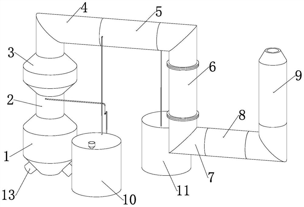
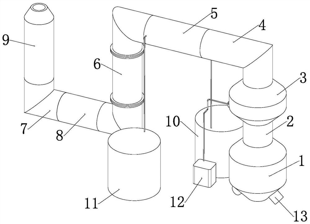
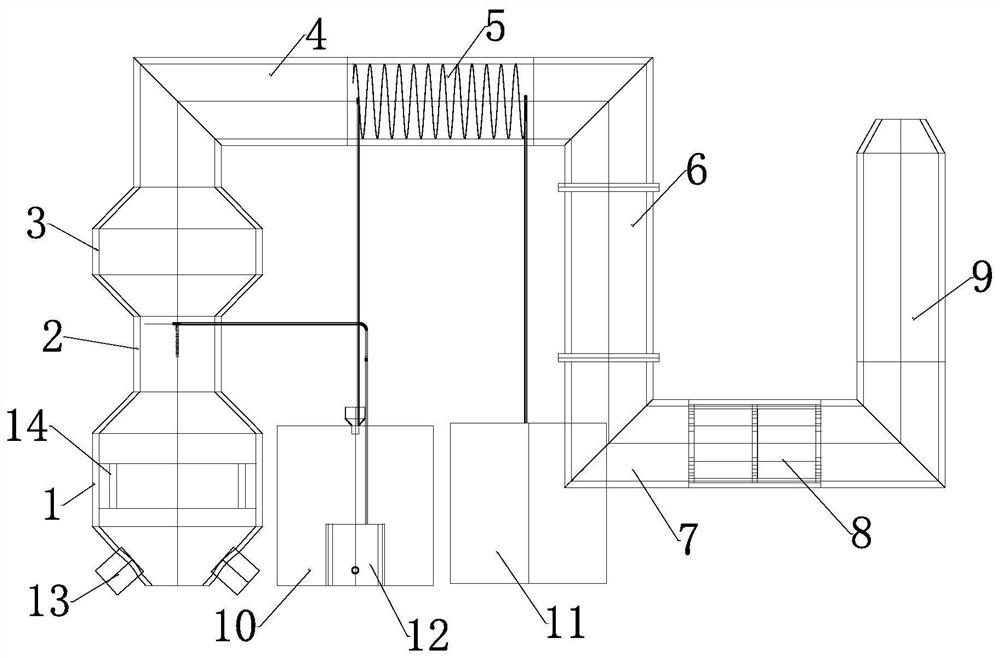
[0032] see Figure 1-8 , the present invention provides a technical solution: a cement kiln flue gas denitrification device with waste heat recovery, including a heating frame 1, a liquid-repellent mechanism 2, a reaction frame 3, a waste heat recovery mechanism 5, a bag filter 6, and a secondary reaction mechanism 8. The reducing agent mixer 10, the water delivery system 11 and the high-pressure liquid-repellent system 12, the upper outlet of the heating fram...


PUM


Abstract

The invention discloses a cement kiln flue gas denitration device with a waste heat recovery function and a denitration method. The cement kiln flue gas denitration device comprises a heating frame, aliquid dispersion mechanism, a reaction frame, a waste heat recovery mechanism, a bag-type dust collector, a secondary reaction mechanism, a reducing agent mixer, a water delivery system and a high-pressure liquid dispersion system, wherein an upper outlet of the heating frame communicates with a lower inlet of the liquid dispersion mechanism, and an upper outlet of the liquid dispersion mechanism communicates with a lower inlet of the reaction frame. By arrangement of the liquid dispersion mechanism and the matched use of the reducing agent mixer and the high-pressure liquid dispersion system, and a mixed reducing agent and flue gas can be completely mixed and enter the reaction frame for primary non-catalytic reduction reaction, so that the denitration efficiency of the flue gas is effectively improved; The secondary reaction mechanism is arranged and matched with the bag-type dust collector for use, and multiple groups of plate-type catalysts are used for carrying out secondary catalytic reduction reaction denitration on flue gas still containing a small amount of NOx, so that the denitration efficiency of the flue gas is further improved.

Description

technical field [0001] The invention relates to the technical field of flue gas treatment, in particular to a cement kiln flue gas denitrification device and a denitrification method with waste heat recovery. Background technique [0002] During the production of cement, NO x The total emissions rank second in industrial emissions, second only to the power industry. Among them, the power industry and the steel industry have implemented ultra-low NO x Therefore, the national emission standards for pollutants in the cement industry are becoming increasingly stringent. [0003] At present, my country's cement industry generally adopts selective non-catalytic reduction technology for denitrification of cement kiln flue gas. However, the removal efficiency is relatively low, and ammonia escape is serious, which cannot meet the existing emission standards. When the flue gas is denitrified, the recovery efficiency of waste heat is also relatively low, which will cause heat loss du...

Claims


Application Information

Patent Timeline
Patent Type & Authority Applications(China)
IPC IPC(8): F27D17/00
CPCF27D17/004F27D17/008F27D2017/006Y02P10/25
Inventor 不公告发明人
Owner 盛培培
Why Eureka
Try Eureka