
Brake disc machining robot feeding and discharging production line and production method

A brake disc and robot technology, applied in metal processing machinery parts, metal processing, metal processing equipment and other directions, can solve the problems of high labor intensity of workers, low product qualification rate, low degree of automation, etc., to improve production safety and security. The effect of personal safety and high degree of automation

Active Publication Date: 2021-02-02
青岛智研自动化设备有限公司
View PDF12 Cites 6 Cited by
  • Summary
  • Abstract
  • Description
  • Claims
  • Application Information

AI Technical Summary

Problems solved by technology

[0007] The invention discloses a brake disc machining robot loading and unloading production line and production method, which solves the problems of low automation in brake disc finishing production, high labor intensity of workers, bad working environment and low production efficiency existing in the prior art. And the problem of low product qualification rate, and the production line disclosed by the present invention has a higher degree of automation, and has higher production efficiency, and can ensure higher production efficiency and product qualification rate at the same time, which is conducive to improving the production capacity of enterprises and at the same time Reduce the production cost of the enterprise; in addition, the production method disclosed in the present invention can further improve the processing efficiency of the brake disc, and at the same time can ensure a higher product qualification rate

Method used


Image

  • Brake disc machining robot feeding and discharging production line and production method
  • Brake disc machining robot feeding and discharging production line and production method
  • Brake disc machining robot feeding and discharging production line and production method

Examples


Embodiment Construction

[0046] Below in conjunction with accompanying drawing and example the present invention will be further described:

[0047] Embodiments of the present invention are described in detail below, examples of which are shown in the drawings, wherein the same or similar reference numerals designate the same or similar elements or elements having the same or similar functions throughout. The embodiments described below by referring to the figures are exemplary only for explaining the present invention and should not be construed as limiting the present invention.

[0048] In the description of the present invention, it should be noted that unless otherwise specified and limited, the terms "installation", "connection" and "connection" should be understood in a broad sense, for example, it can be a fixed connection or a detachable connection. Connected, or integrally connected; either directly or indirectly through an intermediary. Those of ordinary skill in the art can understand the...


PUM


Abstract

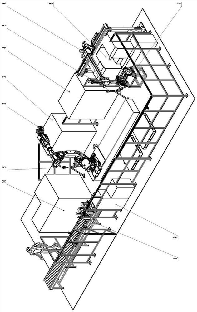
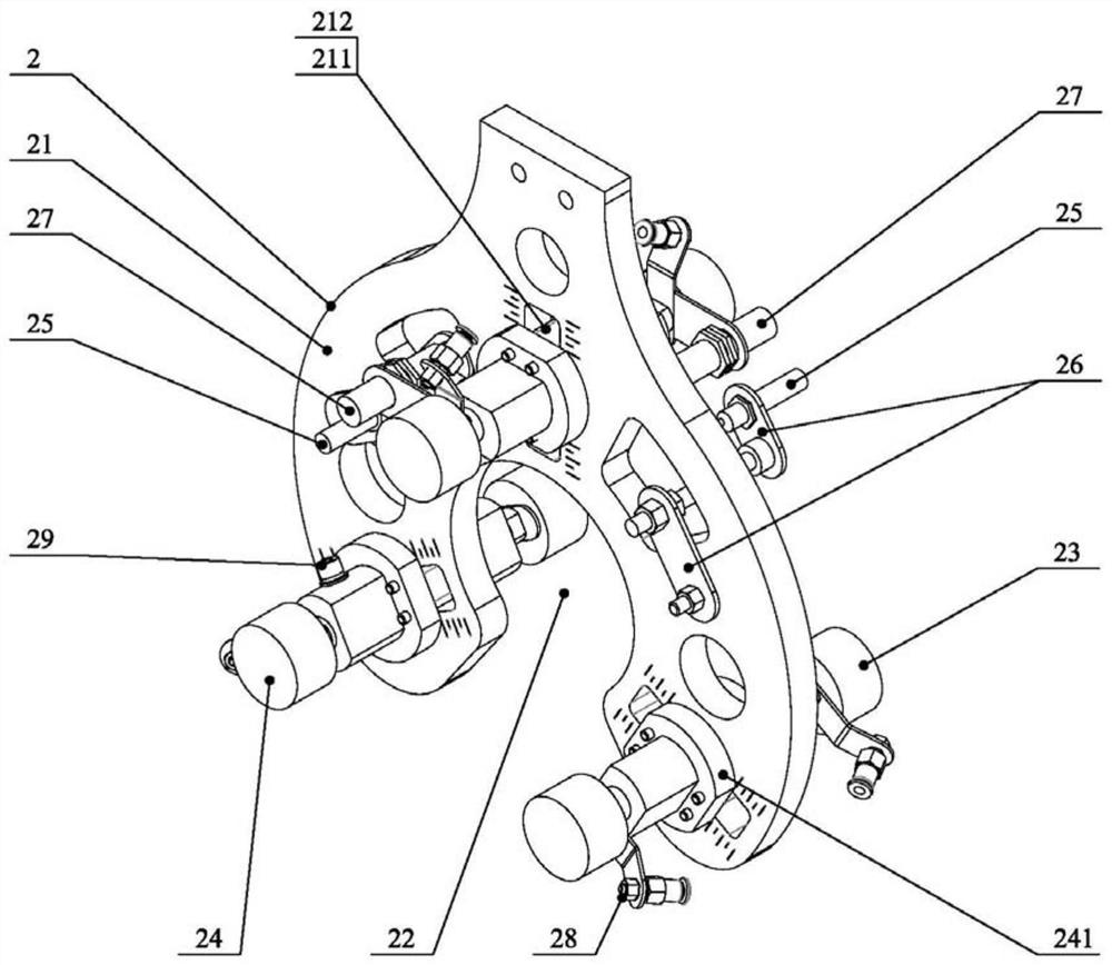
The invention discloses a brake disc machining robot feeding and discharging production line and a production method. The brake disc machining robot feeding and discharging production line comprises an auxiliary feeding system, a first numerical control machine tool, a second numerical control machine tool, a machining center, a grinding machine tool, an auxiliary turnover mechanism, an auxiliarytransfer mechanism, a truss manipulator, a mechanical clamping jaw, an industrial robot and a control cabinet, wherein the industrial robot comprises a ground rail, a robot body arranged on the groundrail, a robot arm connected to the robot body and a robot jig connected to the tail end of the robot arm; the control cabinet controls the robot body, the robot arm and the robot jig to act; and under the control of the control cabinet, a brake disc sequentially finishes the machining process on the first numerical control machine tool, the second numerical control machine tool, the machining center and the grinding machine tool. The production line has high automation degree, production efficiency and percent of pass of products. According to the production method, the brake disc machining efficiency can be further improved, and the enterprise production cost is reduced.

Description

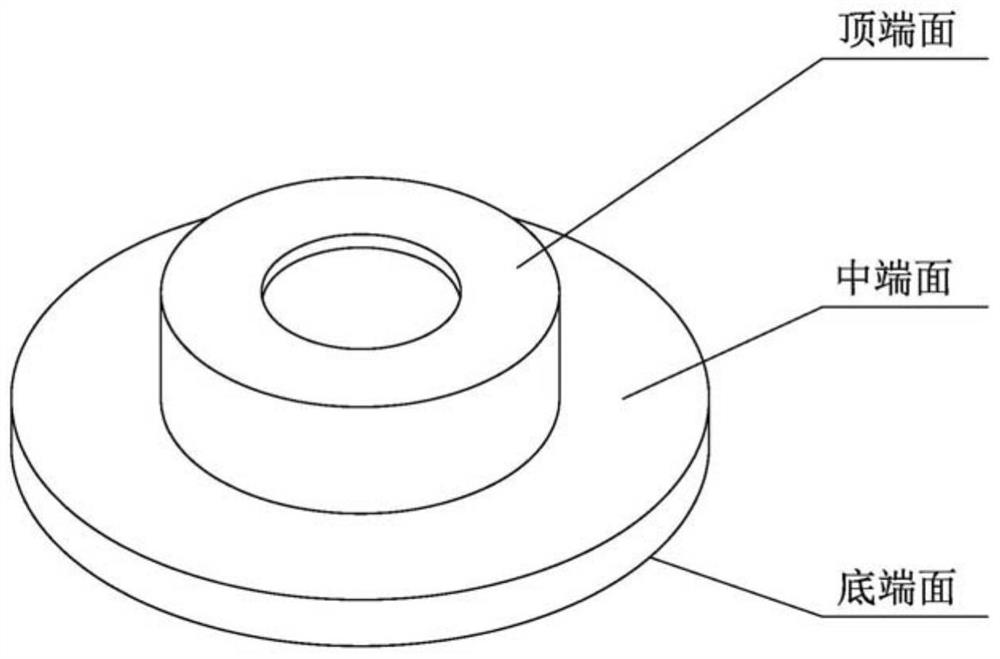
technical field [0001] The invention relates to the technical field of disc workpiece processing, in particular to a brake disc machining robot loading and unloading production line and production method. Background technique [0002] At present, in the brake disc production industry, manual loading and unloading is generally used in the finishing process of brake discs. And the entire production process generally includes 2 CNC lathes, 1 machining center, and 1 grinding machine (this can avoid multiple tool adjustments on the machine tool, which is conducive to improving production efficiency), and generally requires 3 workers per shift Operators, one of whom is in charge of 2 CNC lathes (finishing the middle end face and bottom end face of the brake disc), one operator is in charge of one machining center (drilling, tapping mounting holes, cooling holes and the top surface), and one The operator takes care of a grinding machine (grinding the decorative pattern on the brak...

Claims


Application Information

Patent Timeline
Patent Type & Authority Applications(China)
IPC IPC(8): B23Q3/154B23Q7/04
CPCB23Q3/1543B23Q7/04
Inventor 王佳佳谢通张晓波赵昌龙
Owner 青岛智研自动化设备有限公司
Learn More