
Enhanced heat exchange fin

A technology to enhance heat transfer and fins, applied in heat exchange equipment, lighting and heating equipment, tubular elements, etc., can solve the problems of ineffective enhancement of heat transfer, insufficient improvement of field synergy, and increased fluid resistance, etc., to achieve improved The degree of synergy, the reduction of product cost, and the effect of enhancing heat transfer performance

Pending Publication Date: 2021-01-29
BEIJING SHOUHANG IHW RESOURCES SAVING TECH CO LTD
View PDF0 Cites 0 Cited by
  • Summary
  • Abstract
  • Description
  • Claims
  • Application Information

AI Technical Summary

Problems solved by technology

At present, the use of slotted fins is a relatively effective way to enhance heat exchange. A louvered slotted fin is also disclosed in the prior art, and all the strips have the same twist angle. These fin slotted schemes Although the heat transfer performance is improved, the fluid resistance will increase significantly, and the processing is more difficult
If the number of slots is relatively small, the disturbance to the fluid and the damage to the boundary layer of the air flow will be relatively small, and the field synergy is not improved enough to effectively enhance heat transfer.

Method used


Image

  • Enhanced heat exchange fin
  • Enhanced heat exchange fin
  • Enhanced heat exchange fin

Examples


Embodiment Construction

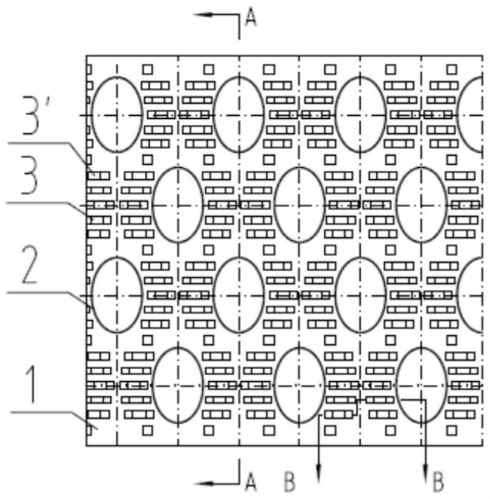
[0019] The present invention will be described in further detail below in conjunction with the embodiment given with accompanying drawing.

[0020] Such as Figure 1-3 As shown, the enhanced heat exchange fin of the present invention includes a fin body 1 and multiple rows of parallel heat exchange base tube penetration holes 2 opened on the fin body 1, and any two adjacent heat exchange base tubes in each row Bridge-shaped protrusions 3, 3' with different heights are opened between the piercing holes 2, and each of the bridge-shaped protrusions 3, 3' passes through two piercing holes 2 of the heat exchange base tube along the direction of air flow. Center line symmetrical arrangement. The two ends 5, 5' of the bridge-shaped protrusions 3, 3' are connected to the fin body 1, and are inclined surfaces forming an angle of less than or equal to 90 degrees with the fin body 1. The tops 4, 4' of the bridge-shaped protrusions 3, 3' are rectangular, parallel to the fin body 1, and ...


PUM


Abstract

The invention relates to an enhanced heat exchange fin and a finned tube heat exchanger. The enhanced heat exchange fin comprise a fin body, a plurality of rows of parallel heat exchange base tube penetrating holes formed in the fin body, and bridge-shaped protrusions which are formed between any two adjacent heat exchange base tube penetrating holes in each row and are different in height, and each bridge-shaped protrusion is symmetrically arranged through the center lines of the two heat exchange base tube penetrating holes in the air flowing direction. Heat exchange can be rapidly and effectively achieved through the heat exchange base tube penetrating holes, and when a fluid flows through the bridge-shaped protrusions with different heights, a boundary layer of the fluid on the surfaceof the enhanced heat exchange fin can be damaged; and disturbance of the fluid is increased, so that the cooperation degree of the flowing speed of the fluid and the temperature gradient is improved,the heat exchange performance is enhanced, and due to the fact that the positions of the heat exchange base tube penetrating holes and the bridge-shaped protrusions are properly selected, fluid resistance is not increased much, thus the heat transfer performance of the finned tube heat exchanger is greatly improved, the size of the heat exchange equipment is reduced, and the product cost is reduced.

Description

technical field [0001] The invention relates to an enhanced heat exchange fin, and products using the enhanced heat exchange fin type can be applied to evaporators and condensers of refrigeration and air-conditioning equipment; intercoolers of air compressors; thermal power plants, nuclear power plants and other fields. air cooling system. Background technique [0002] With air-cooled heat exchangers, the cooling medium flows inside the tubes and the air flows outside the tubes. Since most of the thermal resistance in the heat transfer process is on the air side, in order to enhance heat transfer, fins are usually installed on the air side to enhance heat transfer. The heat exchange area of ​​the device reduces the thermal resistance of the air side. [0003] Generally used fins in the prior art include corrugated fins, straight fins and slotted fins. Corrugated fins are formed by pressing corrugations on the fins along the flow direction. Due to the continuous change of t...

Claims


Application Information

Patent Timeline
Patent Type & Authority Applications(China)
IPC IPC(8): F28F3/00F28F1/02F28F1/12
CPCF28F3/00F28F1/02F28F1/12
Inventor 李会利
Owner BEIJING SHOUHANG IHW RESOURCES SAVING TECH CO LTD
Learn More