
Lens edging machine

A technology for edging machines and lenses, which is applied to grinding frames, machine tools suitable for grinding the edge of workpieces, and parts of grinding machine tools, etc. It can solve the problems of affecting the quality of lens edging, low processing efficiency, and high equipment temperature. , to achieve the effect of saving working time, improving processing efficiency and improving quality

Inactive Publication Date: 2021-01-26
江西中奥塑胶有限公司
View PDF1 Cites 3 Cited by
  • Summary
  • Abstract
  • Description
  • Claims
  • Application Information

AI Technical Summary

Problems solved by technology

[0006] 1. A pair of glasses includes left and right lenses, and the lens edging device is only equipped with one station, and the left lens and the right lens need to be processed separately to complete the assembly of a pair of glasses, and the lens edging device edging the whole process It requires manual operation by employees, which has low processing efficiency and takes a long time;
[0007] 2. The process of lens edging is accompanied by heat generation, and long-term grinding can easily cause the temperature of the equipment to be too high, which will affect the quality of lens edging

Method used


Image

  • Lens edging machine
  • Lens edging machine
  • Lens edging machine

Examples


Embodiment Construction

[0034] Embodiments of the present invention are described in detail below, examples of which are shown in the drawings, wherein the same or similar reference numerals designate the same or similar elements or elements having the same or similar functions throughout. The embodiments described below by referring to the figures are exemplary and are intended to explain the present invention and should not be construed as limiting the present invention.

[0035] In describing the present invention, it should be understood that the terms "length", "width", "upper", "lower", "front", "rear", "left", "right", "vertical", The orientation or positional relationship indicated by "horizontal", "top", "bottom", "inner", "outer", etc. are based on the orientation or positional relationship shown in the drawings, and are only for the convenience of describing the present invention and simplifying the description, rather than Nothing indicating or implying that a referenced device or element...


PUM


Abstract

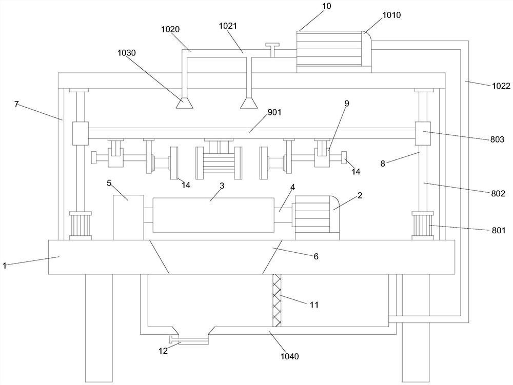
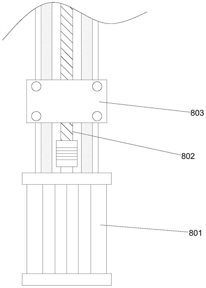
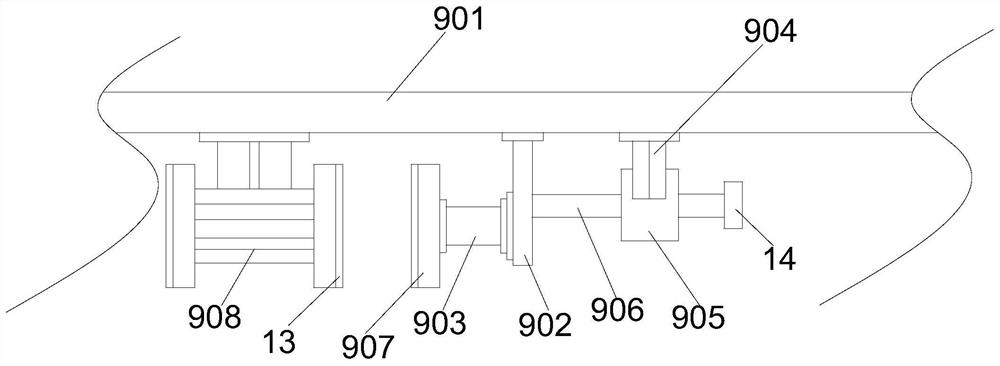
The invention provides a lens edging machine. The lens edging machine comprises a workbench, a first motor, a grinding wheel, a bearing and a fixed block, and further comprises a protective cover, anelectric lead screw device, a clamping device and a cooling device, wherein the first motor, the grinding wheel, the bearing and the fixed block are positioned on the top of the workbench; the grinding wheel is positioned on the bearing; one end of the bearing is connected to the first motor, and the other end of the bearing is connected to the fixed block; a water collecting hopper is arranged inside the workbench; the protective cover is a movable type protective cover, and is positioned on the top of the workbench; and the electric lead screw device, the clamping device and the cooling device are positioned inside the protective cover. The lens edging machine provided by the invention is equipped with dual stations, so that left and right lenses can be automatically edged at the same time, and thus, processing efficiency is improved, and working time is saved; a cooling device is arranged, and a water-cooling way is adopted for cooling the to-be-edged lenses, so that edging qualityof the lenses is improved; and meanwhile, cyclic utilization of water resources is realized through a water pump, a water tube and a filter screen.

Description

technical field [0001] The invention relates to the technical field of lens processing equipment, in particular to a lens edger. Background technique [0002] The lens is also called the mirror heart, which is the painting heart after mounting. It is suitable for being placed in the frame, so it is called the mirror heart. Its form can be horizontal or vertical. It is a simple and convenient installation. It can be mainly divided into glass lenses, resin lenses, PC lenses, etc. Lenses can be divided into daily general-purpose lenses, protective lenses, and multi-focus lenses according to their functions. Lenses on the market usually include spherical, aspherical, double-sided aspheric, single Visual design such as light or multi-focus, good visual design can improve the reality of visual objects, relieve eye fatigue, and improve the wearing experience of consumers. [0003] Lenses often need to be edged during production and processing. The edging of the lens is not only be...

Claims


Application Information

Patent Timeline
Patent Type & Authority Applications(China)
IPC IPC(8): B24B9/02B24B13/00B24B41/02B24B41/04B24B41/06B24B47/12B24B47/20B24B47/22B24B55/03B24B55/06B24B55/12
CPCB24B9/02B24B13/00B24B41/02B24B41/04B24B41/06B24B47/12B24B47/20B24B47/22B24B55/03B24B55/06B24B55/12
Inventor 吴帅陈倍倍冯旭
Owner 江西中奥塑胶有限公司
Learn More