Luneberg lens antenna applied to S waveband

A Lumberg lens antenna, band technology, applied in the directions of separately powered antenna array, antenna, antenna coupling, etc., can solve the problems of limitation, heavy sphere weight, inability to use multiple feeds, etc., and achieve large working bandwidth and high gain. , the effect of many beam coverage capabilities

Pending Publication Date: 2021-01-12
江苏晨创科技有限公司
View PDF0 Cites 2 Cited by
  • Summary
  • Abstract
  • Description
  • Claims
  • Application Information

AI Technical Summary

Problems solved by technology

In practical applications, the application of small-sized lenses is of little significance. Because the size is too small, multiple feed sources cannot be used. The difficulty of using large-sized Lunberg lenses is that the volume is relatively large, which leads to excessive weight of the sphere and is not easy to fix, especially in limited space. In aircraft and ships, these problems greatly limit the application of conventional spherical Lunberg lenses

Method used


Image

  • Luneberg lens antenna applied to S waveband
  • Luneberg lens antenna applied to S waveband
  • Luneberg lens antenna applied to S waveband

Examples


Embodiment Construction

[0025] In order to make the purpose, technical solutions and advantages of the embodiments of the present invention clearer, the technical solutions in the embodiments of the present invention will be clearly and completely described below in conjunction with the accompanying drawings in the present invention. Obviously, the described embodiments are the Some embodiments of the invention are not all embodiments. Based on the embodiments of the present invention, all other embodiments obtained by those of ordinary skill in the art without creative efforts fall within the protection scope of the present invention.

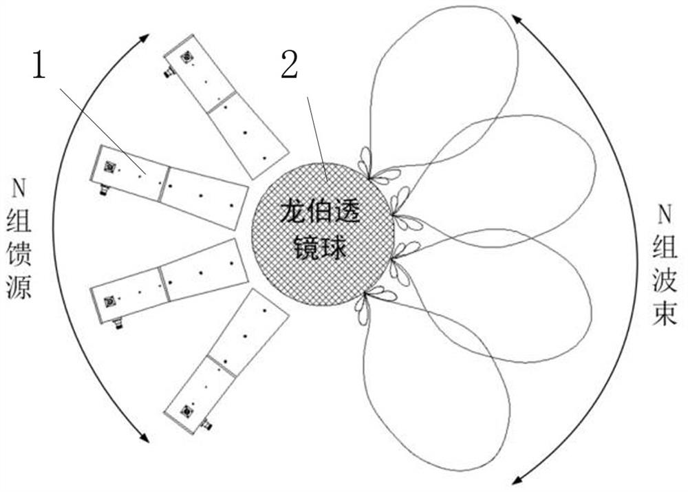
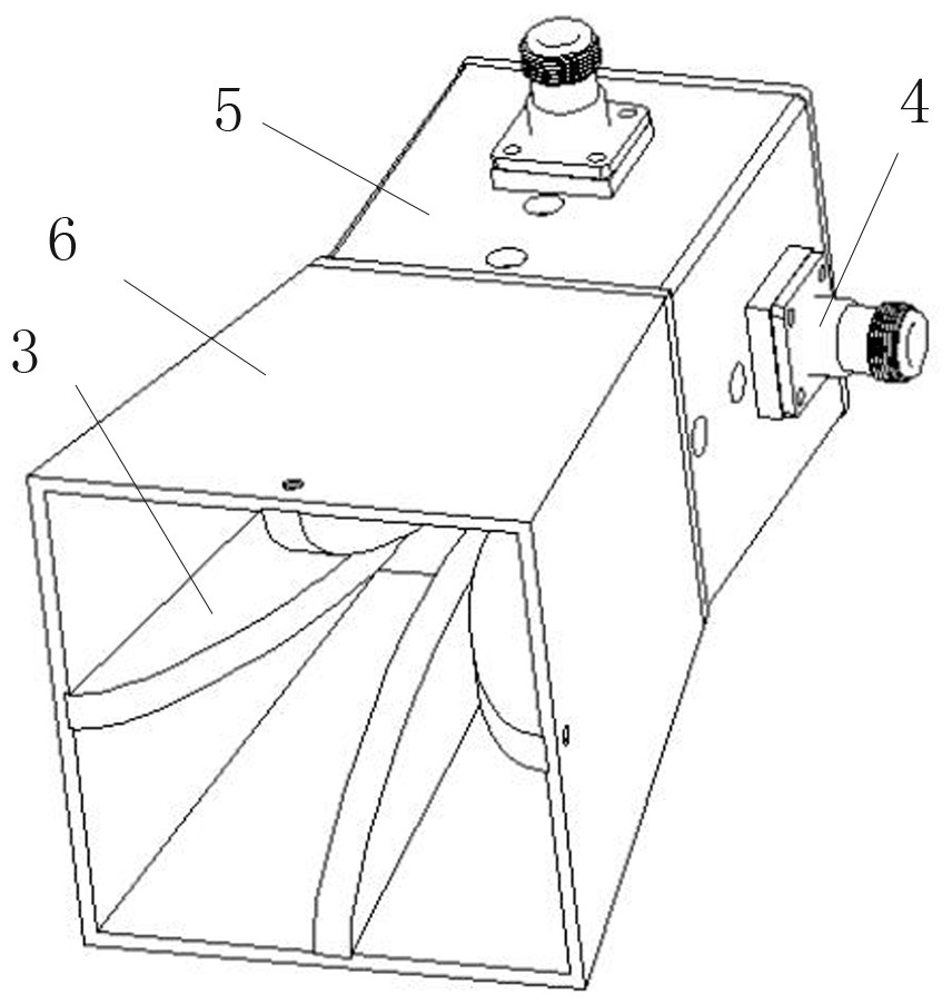
[0026] A Lunberg lens antenna applied to the S band, such as figure 1 As shown, it mainly includes two parts: the feed array and the dielectric sphere 2. The feed array is evenly distributed along the periphery of the dielectric sphere to generate N groups of wide beams with different radiation directions. After being focused by the dielectric sphere, the beam becomes...


PUM


Abstract

The invention provides a luneberg lens antenna applied to an S waveband, which comprises dielectric spheres and a feed source array used for realizing beam control and scanning capability, the feed source array is uniformly arranged along the peripheries of the dielectric spheres, and the dielectric spheres adopt a layered structure. Materials of each layer of structure of the dielectric sphere include but are not limited to high-dielectric-constant materials such as polystyrene and barium copper titanate. By optimizing the dielectric constant and the thickness of each layer of structure of the dielectric spheres, the convergence effect of the dielectric spheres on feed source array beams is adjusted, the standing-wave ratios of the horn feed source at two cross polarization ports of 1.7 GHz and 2.7 GHz can be smaller than 1.5, and the isolation degree between the feed source ports is larger than 30 dB. Moreover, after the dielectric lens is added, the wave beam width of the lens is obviously narrowed compared with the wave beam width of the feed source, so that the antenna provided by the invention has higher gain, larger working bandwidth and better wave beam coverage capability.

Description

technical field [0001] The invention belongs to the technical field of antennas, and in particular relates to a Lunberg lens antenna applied to the S-band. Background technique [0002] With the rapid development of satellite communication technology, many new and stricter requirements are put forward for the ground station antenna. For example, characteristics of wide frequency band, high gain, multi-beam and wide scanning angle are required. In addition, with the development of digital satellite live broadcast services, the demand for first-line multi-satellite services is imminent. In traditional satellite communication, parabolic antennas are often used to make high-gain antennas for ground stations. However, with the upgrading of satellite communication technology, especially in the "moving communication" technology of mobile satellite communication systems, the shortcomings of parabolic antennas are gradually exposed. For example, the focus position of a parabolic an...

Claims


Application Information

Patent Timeline
Patent Type & Authority Applications(China)
IPC IPC(8): H01Q1/52H01Q13/02H01Q19/06H01Q21/20
CPCH01Q1/523H01Q13/0275H01Q19/06H01Q21/20
Inventor 王宏庆姚丹戚泽超张祖球
Owner 江苏晨创科技有限公司
Why Eureka
Try Eureka