
Light-weight optical antenna and method for realizing capturing and tracking based on light-weight optical antenna

An optical antenna, lightweight technology, applied in optics, optical components, nonlinear optics, etc., can solve the problems of small area of ​​wedge-shaped dual-frequency liquid crystal phased array, uneven response time, slow response of optical antenna, etc. Light area requirements, consistent response time, light weight

Active Publication Date: 2021-01-12
XI'AN INST OF OPTICS & FINE MECHANICS - CHINESE ACAD OF SCI
View PDF6 Cites 2 Cited by
  • Summary
  • Abstract
  • Description
  • Claims
  • Application Information

AI Technical Summary

Problems solved by technology

[0006] The purpose of the present invention is to propose a novel lightweight optical antenna and a method for capturing and aiming based on it, so as to overcome the large weight and power consumption of the traditional mechanical turntable optical antenna, the slow response of the optical antenna based solely on liquid crystal phased array, and the wedge-shaped double-sided antenna. The problem that the area of ​​the high-frequency liquid crystal phased array is too small and the response time is uneven

Method used


Image

  • Light-weight optical antenna and method for realizing capturing and tracking based on light-weight optical antenna
  • Light-weight optical antenna and method for realizing capturing and tracking based on light-weight optical antenna
  • Light-weight optical antenna and method for realizing capturing and tracking based on light-weight optical antenna

Examples


Embodiment Construction

[0071] The present invention will be further described below in conjunction with the accompanying drawings and specific embodiments.

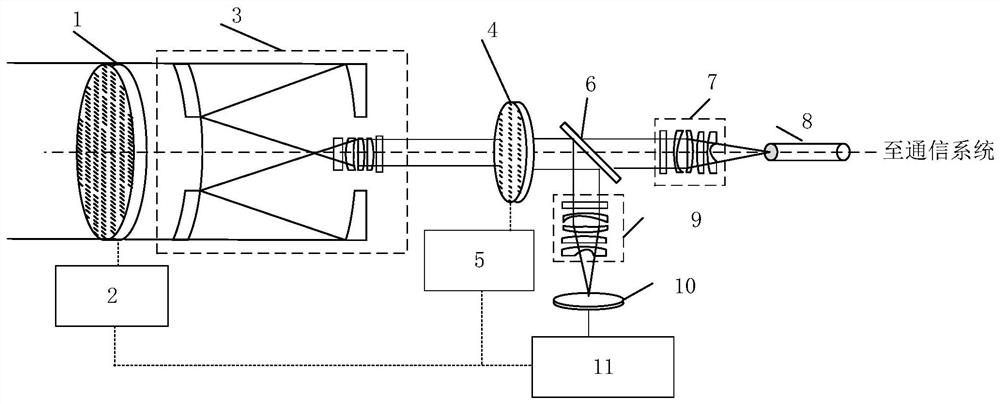
[0072] refer to figure 1 , the new lightweight optical antenna of this embodiment is used to establish a laser link between two laser terminals in space, specifically including a rough tracking liquid crystal 1, a rough tracking liquid crystal controller 2, a beam shrinking system 3, a fine tracking liquid crystal 4, a fine tracking liquid crystal Tracking liquid crystal controller 5 , beam splitter 6 , first coupling system 7 , single-mode optical fiber 8 , second coupling system 9 , detector 10 and data analysis and instruction system 11 .

[0073] Among them, the coarse tracking liquid crystal 1, the shrinkage system 3, the fine tracking liquid crystal 4, the beam splitter 6, the first coupling system 7 and the single-mode fiber 8 are arranged in sequence from left to right, and are located on the same central axis; the beam splitter 6 and t...


PUM


Abstract

The invention discloses a light-weight optical antenna and a method for realizing capturing and tracking based on the light-weight optical antenna. The problems that a traditional mechanical rotary table type optical antenna is extremely large in weight power consumption, slow in response based on a liquid crystal phased array optical antenna purely, too small in wedge-shaped double-frequency liquid crystal phased array area and uneven in response time are solved. The antenna comprises a coarse tracking liquid crystal, a coarse tracking liquid crystal controller, a beam shrinking system, a fine tracking liquid crystal, a fine tracking liquid crystal controller, a spectroscope, a first coupling system, a single-mode optical fiber, a second coupling system, a detector and a data analysis andinstruction system. The antenna can be used for receiving a laser beam of a communication target and emitting the laser beam to the communication target. According to the optical antenna, capturing and tracking of space laser beams are achieved through cascade connection of two stages of liquid crystal devices, and compared with a mechanical rotary table type optical antenna, the optical antennahas the advantages of being small in size, light in weight and low in power consumption; meanwhile, high-precision pointing change of light beams is achieved through deflection of the double-state double-frequency liquid crystal, and the advantages of being fast in light beam pointing and short in response time are achieved.

Description

technical field [0001] The invention belongs to the field of space laser communication, and specifically relates to a novel light-weight optical antenna, and a method for capturing and tracking light beams of space laser communication based on the optical antenna. Background technique [0002] Because of its advantages of high speed and good confidentiality, space laser communication has become the necessary technical way for the backbone link of space information network. On-orbit demonstration verification. In order to build a complete space information network, a number of demonstration and verification programs related to space laser communication have been deployed at home and abroad. [0003] In the space laser communication system, the optical antenna is the core part of the establishment of the space laser link and the stable transmission of high-speed data. Its function is to capture the laser link to be transmitted, and quickly track and aim to make the beam stab...

Claims


Application Information

Patent Timeline
Patent Type & Authority Applications(China)
IPC IPC(8): G02F1/13G02F1/133G02B6/26G02B6/32G02B27/09H04B10/11
CPCG02F1/13G02F1/133G02B6/26G02B27/0927G02B6/32H04B10/11H01Q3/2676
Inventor 谢小平黄新宁汪伟赵意意
Owner XI'AN INST OF OPTICS & FINE MECHANICS - CHINESE ACAD OF SCI
Learn More