Cooling and dewatering device for automobile exhaust pipe

A technology for automobile exhaust and exhaust pipes, which is applied in the direction of exhaust devices, mufflers, engine components, etc., which can solve the problems of poor exhaust cooling effect and exhaust pipe blockage, and achieve a good cooling effect

Active Publication Date: 2021-01-12
LIUZHOU TONGSHUN AUTO PARTS
View PDF10 Cites 2 Cited by
  • Summary
  • Abstract
  • Description
  • Claims
  • Application Information

AI Technical Summary

Problems solved by technology

[0005] The purpose of the present invention is to provide a cooling and water removal device for automobile exhaust pipes with good cooling effect and water removal function for the above-mentioned problems that the cooling effect of exhaust gas is poor and the condensed water is easy to cause blockage of the exhaust pipe

Method used


Image

  • Cooling and dewatering device for automobile exhaust pipe
  • Cooling and dewatering device for automobile exhaust pipe

Examples


Embodiment 1

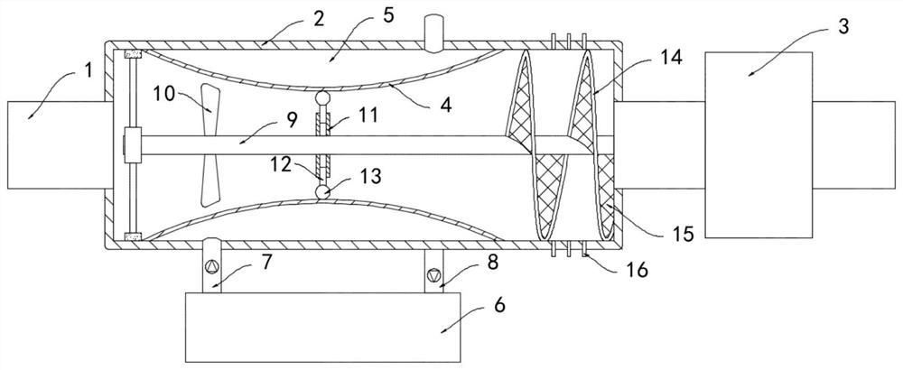
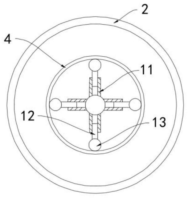
[0016] Such as Figure 1-2 As shown, a cooling and dewatering device for an automobile exhaust pipe includes an exhaust pipe 1, and the exhaust pipe 1 is sequentially connected with a cooling box 2 and a purification muffler 3, and the cooling box 2 is arranged coaxially with the exhaust pipe 1. The cylindrical structure, the inner wall of the cooling box 2 is equipped with a deformation tube 4, both ends of the deformation tube 4 are fixed and sealed with the inner wall of the cooling box 2, the section of the deformation tube 4 is dumbbell-shaped and connected to the A coolant cavity 5 is formed between them, and a return box 6 is provided outside the cooling box 2, and the return box 6 communicates with the coolant cavity 5 through a one-way liquid inlet pipe 7 and a one-way liquid discharge pipe 8, and a cooling box 2 is provided along its axis. The rotating shaft 9 extending in the direction, the fan 10 is installed coaxially outside the rotating shaft 9, and a plurality ...

Embodiment 2

[0021] Such as Figure 1-2 As shown, the difference between this embodiment and Embodiment 1 is that: the weight ball 13 is made of magnetic material, and the spring 14 is an electromagnetic spring.

[0022] In this embodiment, according to the principle of electromagnetic induction, when the magnetic flux in the closed coil changes, an induced current will be generated in the closed coil, and when the weight ball 13 rotates with the rotating shaft 9, the magnetic flux in the spring 14 will change, resulting in Induce current and generate an induced magnetic field, and each coil of the electromagnetic spring 14 produces a small magnetic coil with the same magnetic pole, and under the action of the induced magnetic field, the electromagnetic spring 14 is driven to shrink, thereby driving the water filter net 15 to shrink, further improving the moisture absorption in the exhaust gas. After the counterweight ball 13 stops rotating, the induced magnetic field in the spring 14 disa...


PUM


Abstract

The invention belongs to the technical field of ecological environmental protection, and particularly relates to a cooling and dewatering device for an automobile exhaust pipe. The cooling and dewatering device comprises an exhaust pipe, and the exhaust pipe sequentially communicates with a cooling box and a purification silencer in a penetrating manner; the cooling and dewatering device is characterized in that the cooling box is of a cylindrical structure coaxial with the exhaust pipe, a deformation pipe is arranged on the inner side wall of the cooling box, the two ends of the deformation pipe are both fixed and sealed to the inner side wall of the cooling box, the section of the deformation pipe is dumbbell-shaped, and a cooling liquid cavity is formed between the deformation pipe andthe cooling box; and a backflow box is arranged outside the cooling box, the backflow box communicates with the cooling liquid cavity through a one-way liquid inlet pipe and a one-way liquid outlet pipe, and a rotating shaft extending in the axis direction of the cooling box is arranged in the cooling box. According to the cooling and dewatering device, heat in tail gas can be rapidly absorbed through flow exchange between the cooling liquid cavity and cooling liquid in the backflow box, a good cooling effect is achieved, cooled and condensed water is discharged out of the cooling box througha capillary tube, and blockage caused by the fact that the water enters the purification silencer is avoided.

Description

technical field [0001] The invention belongs to the technical field of ecology and environmental protection, and in particular relates to a cooling and dewatering device for an automobile exhaust pipe. Background technique [0002] A large amount of exhaust gas generated when the car is running is discharged through the exhaust pipe. The existing exhaust pipe is equipped with a purification muffler to reduce the content of harmful gases in the exhaust gas and the noise, and reduce the pollution to the environment. When the exhaust gas is discharged from the exhaust valve of the automobile engine, its temperature is as high as 600°C. After the exhaust gas enters the purifying muffler, the high temperature accelerates the aging and loss of the purifying muffler, greatly reducing its service life. [0003] The traditional exhaust gas cooling method is through the circuitous and tortuous passage of the exhaust pipe, prolonging the conduction path of the exhaust gas in the exhaus...

Claims


Application Information

Patent Timeline
Patent Type & Authority Applications(China)
IPC IPC(8): F01N3/02F01N3/04F01N13/08
CPCF01N3/02F01N3/04F01N13/08
Inventor 顾海明
Owner LIUZHOU TONGSHUN AUTO PARTS
Why Eureka
Try Eureka