
A self-radiating and dehumidifying cable trench for communication base stations

A communication base station and self-heating technology, which is applied in the installation of cables, ground cables, electrical components, etc., can solve the problems of hot and humid heat in cable trenches, and it is difficult to dissipate heat, so as to improve dehumidification capacity, reduce moisture content, and heat dissipation effect Good results

Active Publication Date: 2021-12-28
河北鹏博通信设备有限公司
View PDF6 Cites 0 Cited by
  • Summary
  • Abstract
  • Description
  • Claims
  • Application Information

AI Technical Summary

Problems solved by technology

[0005] The purpose of the present invention is to provide a self-radiating and dehumidifying cable trench for communication base stations that can automatically dissipate heat and dehumidify in order to solve the problem that the above-mentioned cable trench is stuffy and humid and the heat is difficult to dissipate.

Method used


Image

  • A self-radiating and dehumidifying cable trench for communication base stations
  • A self-radiating and dehumidifying cable trench for communication base stations
  • A self-radiating and dehumidifying cable trench for communication base stations

Examples


Embodiment 1

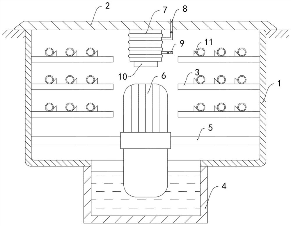
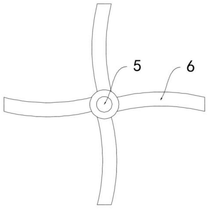
[0021] Such as Figure 1-2 As shown, a self-radiating and dehumidifying cable trench for a communication base station includes a trench body 1 and a cover plate 2, and a plurality of cable racks 3 are installed on the side walls on both sides of the trench body 1, and the upper surfaces of the cable racks 3 are equidistant from each other. A plurality of wedge-shaped limit blocks 11 are arranged, and a drainage channel 4 is opened at the bottom of the ditch body 1. The drainage channel 4 is connected in series in the urban domestic sewage discharge system, and the urban sewage flows through the drainage channel 4 when it is discharged. The inner wall is rotatably connected with a rotating shaft 5 arranged horizontally. A water wheel 6 is installed coaxially outside the rotating shaft 5. The blades of the water wheel 6 extend to the inside of the drainage channel 4. When the sewage in the drainage channel 4 flows, the water wheel 6 can be pushed. turn.

[0022] The lower surfa...

Embodiment 2

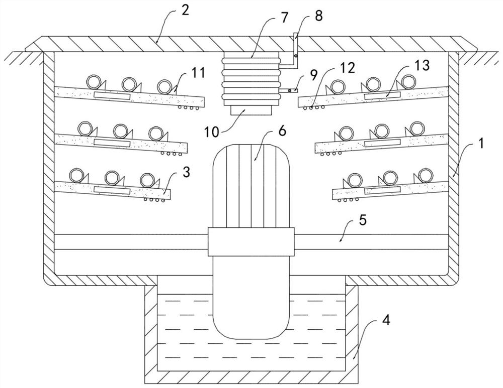
[0025] Such as image 3 As shown, the difference between this embodiment and Embodiment 1 is that the ends of the plurality of cable racks 3 away from the side wall of the ditch body 1 are inclined downward, and the angle with the side wall of the ditch body 1 is 80°. It is convenient for the condensed water droplets on the cable rack 3 to drip downward under the action of gravity, and the lengths of the multiple cable racks 3 are shortened sequentially from top to bottom, so as to avoid blocking and ensure that the water droplets drop into the drainage channel 4, and the water drops along with the sewage Discharge, the lower surface of the cable frame 3 close to the end of the water wheel 6 is coiled by a multi-strand conductor coil 12, the cable frame 3 is embedded with a refrigeration sheet 13, and the two ends of the multi-strand conductor coil 12 are respectively connected to the positive and negative sides of the refrigeration sheet 13. The poles are electrically connect...


PUM


Abstract

The invention belongs to the field of communication facilities, and in particular relates to a self-radiating and dehumidifying cable trench for a communication base station, which includes a trench body and a cover plate, and a plurality of cable racks are installed on the side walls on both sides of the trench body, and is characterized in that, A drainage channel is opened at the bottom of the ditch, and the drainage channel is connected in series with the urban domestic sewage discharge system. A rotating shaft arranged horizontally is rotatably connected to the inner wall of the ditch body. The blades of the water wheel are extended to the drain, the lower surface of the cover plate is fixedly connected with an elastic air bag, and the side wall of the elastic air bag is fixedly connected with a one-way air intake pipe and a one-way exhaust pipe. , the other end of the one-way air intake pipe runs through the cover plate and extends outside the ditch, and the lower end of the elastic airbag is fixedly connected with a permanent magnet block. The present invention can drain the sewage in the ditch to realize rapid cooling in the ditch, and the effect of cooling and dehumidification is improved by the expansion and contraction of the air bag, which is energy-saving and environment-friendly, and ensures a good working environment for cables.

Description

technical field [0001] The invention belongs to the field of communication facilities, in particular to a self-radiating and dehumidifying cable trench for a communication base station. Background technique [0002] With the development of communication network technology, the construction of communication base stations has gradually become the focus of attention. The communication base stations are mainly used to provide wireless coverage and realize wireless signal transmission between wired communication networks and wireless terminals. There are a large number of cables in the communication base stations, so it is necessary to set up cable trenches for the safe and orderly arrangement of a large number of cables. [0003] Most of the traditional cable trenches are equipped with cover plates to prevent rainwater and sundries from entering. The cable trench forms a relatively closed space, and the cables generate a lot of heat when they are in use. If they are not released...

Claims


Application Information

Patent Timeline
Patent Type & Authority Patents(China)
IPC IPC(8): H02G9/02H02G3/03B01D53/26F03B13/00
CPCH02G9/02H02G3/03B01D53/26B01D53/265F03B13/00Y02B10/50
Inventor 梁燕咏石连营
Owner 河北鹏博通信设备有限公司
Learn More