Power distribution cabinet with dust removal and heat dissipation structure

A technology of heat dissipation structure and power distribution cabinet, which is applied in the substation/distribution device casing, electrical components, substation/switch layout details, etc. problems, to ensure patency, to achieve internal and external air exchange, and to facilitate the use of

Active Publication Date: 2021-12-21
佛山市智光智能装备有限公司
View PDF0 Cites 0 Cited by
  • Summary
  • Abstract
  • Description
  • Claims
  • Application Information

AI Technical Summary

Problems solved by technology

[0003] At present, most of the existing power distribution cabinets are simple in structure, which can only meet the basic electrical installation and inefficient heat dissipation. Since more and more electrical components need to be installed in the power distribution cabinet, the installation ratio of high-power electrical components is gradually increasing. Higher, which leads to excessive heat inside the power distribution cabinet; at the same time, a large amount of dust is absorbed in the traditional power distribution cabinet, which will increase the energy consumption of electrical components, resulting in more heat, which intensifies the accumulation of heat inside the power distribution cabinet , Failure to dissipate heat in time can easily lead to aging and damage of electrical components, and even fires. Therefore, we have designed a power distribution cabinet with a dust removal and heat dissipation structure to solve the above problems

Method used


Image

  • Power distribution cabinet with dust removal and heat dissipation structure
  • Power distribution cabinet with dust removal and heat dissipation structure
  • Power distribution cabinet with dust removal and heat dissipation structure

Examples


Embodiment 1

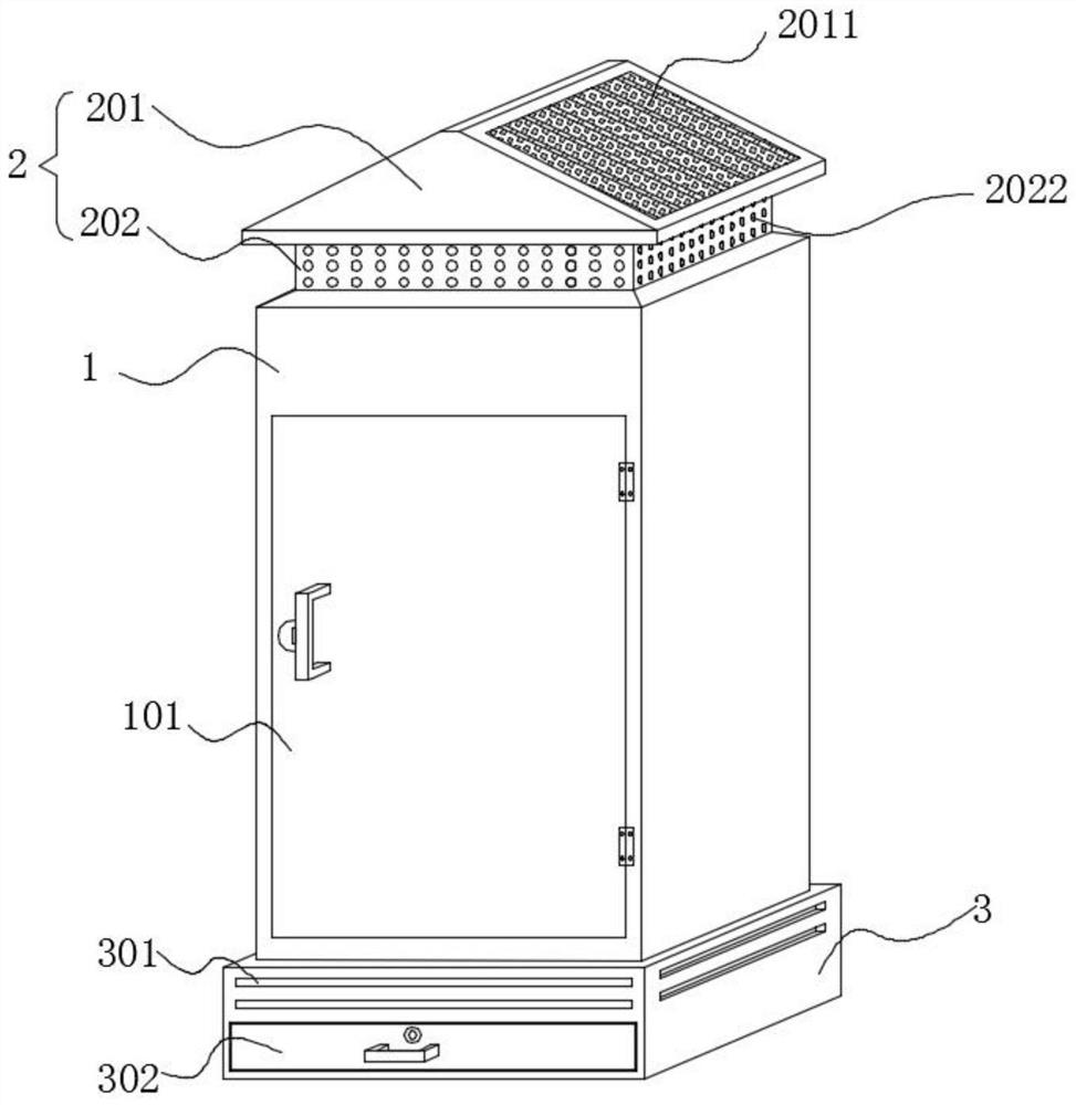
[0032] refer to Figure 1-7 , this embodiment includes a cabinet body 1, a rainproof ceiling 2 and a moisture-proof base 3, the rainproof ceiling 2 and the moisture-proof base 3 are fixedly arranged on the top and bottom of the cabinet body 1 respectively, and the three are connected to each other, and the rainproof ceiling 2 is arranged There are air intake holes 2022;

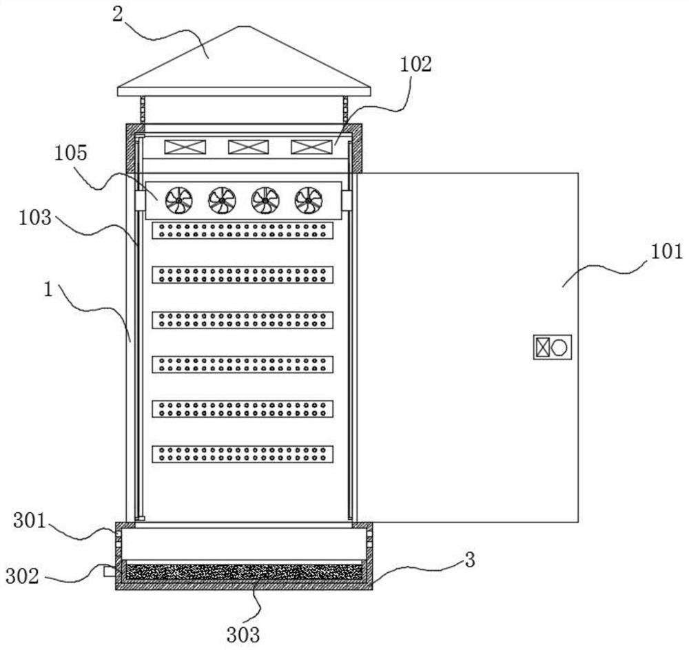
[0033] The top of the cabinet body 1 inner cavity is equipped with a longitudinal cooling mechanism 102, and the cabinet body 1 is located on both sides of the cabinet door 101. Guide rails 103 are installed longitudinally on the inner walls of both sides of the cabinet body 101, and a mobile cooling mechanism 105 is installed between the two guiding rails 103. The heat dissipation mechanism 105 is driven by the drive mechanism 104 to move up and down along the cabinet body 1 to dissipate heat;

[0034] The side wall of the upper half of the moisture-proof base 3 is provided with a heat dissipation window 30...

Embodiment 2

[0046] refer to Figure 1-6 and 8. The difference between this embodiment and Embodiment 1 is that the structure of the mobile cooling mechanism 105 is different. In this embodiment, a rotating groove 1056 is opened in the middle of the moving bracket 1051, and a rotating plate 1057 is installed in the rotating groove 1056 through the rotation of the rotating shaft. , the moving blower fan 1052 is installed on the rotating plate 1057, and the rotating plate 1057 is driven by a motor 1058 installed on the moving bracket 1051.

[0047] In this embodiment, the mobile fan 1052 is installed on the rotating plate 1057, and the motor 1058 drives the mobile fan 1052 on the rotating plate 1057 to swing. When the mobile cooling mechanism 105 moves up and down, the mobile fan 1052 can swing at a certain angle. Dust is blown from multiple angles, which further improves the dust removal effect on the surface of electrical components.

Embodiment 3

[0049] refer to Figure 4 In this embodiment, multiple sets of temperature sensors 106 are added, and multiple sets of temperature sensors 106 are installed equidistantly from top to bottom on the inner wall of the cabinet body 1 .

[0050] In this embodiment, the temperature sensor 106 can monitor the temperature of each position of the inner cavity of the cabinet body 1 in real time in different regions. The efficiency of heat dissipation is greatly improved, and precise and rapid heat dissipation is realized.


PUM


Abstract

The invention discloses a power distribution cabinet with a dust removal and heat dissipation structure, relates to the field of dental treatment instruments, and comprises a cabinet body, a rain-proof ceiling and a moisture-proof base, the rain-proof ceiling is provided with an air inlet; the top of the cabinet inner cavity A longitudinal heat dissipation mechanism is installed, and the inner wall of the cabinet body is located on both sides of the cabinet door. Guide rails are installed along the longitudinal direction, and a mobile heat dissipation mechanism is installed between the two guide rails. The mobile heat dissipation mechanism is driven by a driving mechanism along the The cabinet body moves up and down to dissipate heat; the side wall of the upper half of the moisture-proof base is provided with a heat-dissipating window, and the bottom of the moisture-proof base is installed with a pull-out dust collection box. The invention realizes the exchange of internal and external air through the flowing air from top to bottom, and at the same time, it can perform local fixed-point heat dissipation to achieve the purpose of improving the heat dissipation effect. The electrostatic adsorption plate on the inside can achieve the purpose of dust removal.

Description

technical field [0001] The invention relates to the field of power distribution cabinets, in particular to a power distribution cabinet with dust removal and heat dissipation structures. Background technique [0002] Power distribution cabinets (boxes) are divided into power distribution cabinets (boxes), lighting distribution cabinets (boxes), and metering cabinets (boxes), which are the final equipment of the power distribution system. The power distribution cabinet is a general term for the motor control center. The power distribution cabinet is used in the occasions where the load is relatively scattered and there are few circuits; the motor control center is used in the occasions where the load is concentrated and there are many circuits. They distribute the electric energy of a certain circuit of the upper-level power distribution equipment to the nearest load. This level of equipment shall provide protection, monitoring and control of the load. [0003] At present,...

Claims


Application Information

Patent Timeline
Patent Type & Authority Patents(China)
IPC IPC(8): H02B1/30H02B1/28H02B1/56
CPCH02B1/30H02B1/28H02B1/565
Inventor 易良腾
Owner 佛山市智光智能装备有限公司
Why Eureka
Try Eureka