
Power supply and distribution box protection device

A protection device and distribution box technology, which is applied in the substation/distribution device housing, substation/switchgear cooling/ventilation, substation/switch layout details, etc. work, etc.

Inactive Publication Date: 2021-01-29
赵媛媛
View PDF0 Cites 4 Cited by
  • Summary
  • Abstract
  • Description
  • Claims
  • Application Information

AI Technical Summary

Problems solved by technology

[0003] Most of the existing distribution boxes are hung on the wall, which is convenient for the staff to operate and control the mechanical work. When workers carry goods, they sometimes hit the distribution box, causing damage to the distribution box and affecting the normal operation of the machine. In addition, the existing distribution box is limited by the terrain of the installation location during installation, and the length of the wiring tube protruding from the bottom of the distribution box needs to be changed to varying degrees. The traditional design can only rely on the flexible configuration at the bottom of the distribution box Adjust the lifting rod to realize the overall lifting of the distribution box, so as to adapt to changing the height of the bottom of the distribution box above the ground. This method is time-consuming and laborious, especially in the follow-up maintenance of the distribution box, it is necessary to repeat the whole distribution box. lifting

Method used


Image

  • Power supply and distribution box protection device
  • Power supply and distribution box protection device
  • Power supply and distribution box protection device

Examples


Embodiment

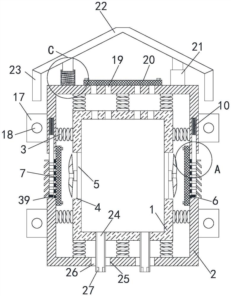
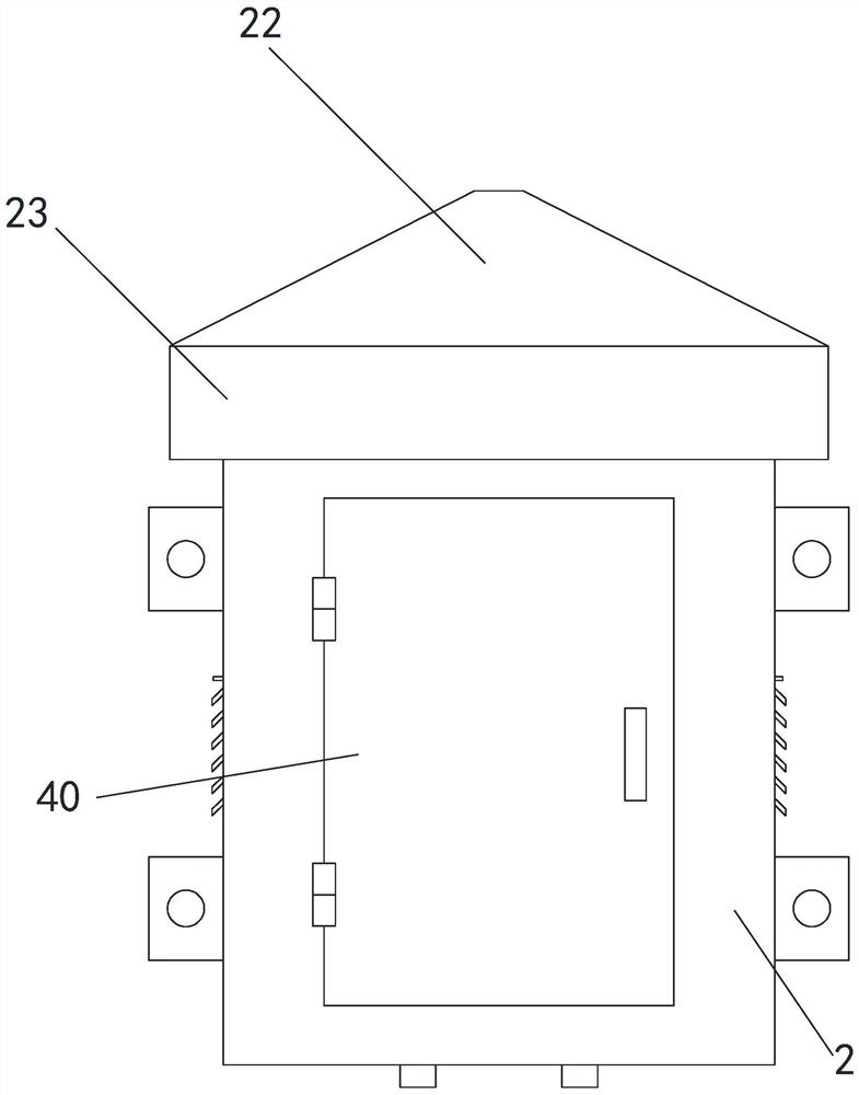
[0032] see Figure 1-7 , a protection device for a power supply and distribution box, the distribution box body 1 is arranged inside the protective box 2, wherein the rear end, left end and right end of the distribution box body 1 are fixedly connected with a plurality of first springs 3, and the rear The first spring 3 at the end, left end and right end is fixedly connected to the inner wall of the protective box 2 at one end far away from the distribution box body 1, and a plurality of first springs 3 are slidably connected to the top and the bottom end of the distribution box body 1, The end of the first spring 3 at the top and the bottom end away from the distribution box body 1 is slidably connected to the inner side wall of the protective box 2, and a first transverse chute is arranged on the top and bottom of the distribution box body 1. The top inner wall and the bottom inner wall of the box 2 are provided with a second transverse chute, the depth of the second transve...


PUM


Abstract

The invention relates to the technical field of power distribution box protection devices, in particular to a power supply and distribution box protection device which comprises a power distribution box body and a protection box, the power distribution box body is arranged in the protection box, and the bottom end, the rear end, the top end, the left end and the right end of the power distributionbox body are fixedly connected with multiple first springs. The ends, away from the distribution box body, of the first springs are fixedly connected with the inner side wall of the protection box, the front end of the distribution box body is in sliding fit with the front inner side wall of the protection box, first through grooves transversely penetrating are formed in the left end and the right end of the distribution box body, and fans are fixedly connected into the first through grooves. Second through grooves are formed in the right end and the left end of the protection box, and the left inner side wall and the right inner side wall of the protection box are located on the outer sides of the second through grooves and fixedly connected with first filter plates through screws; the power distribution box can play a role in shock absorption and protection, the interior of the power distribution box can be cooled, normal work of the power distribution box is guaranteed, and the usepracticability of the power distribution box is improved.

Description

technical field [0001] The invention relates to the technical field of protective devices for power distribution boxes, in particular to a protective device for power supply and distribution boxes. Background technique [0002] As we all know, the distribution box is a large number of parameters in the data, and generally constitutes a low-voltage forest. According to the electrical wiring, it is required to assemble switchgear, measuring instruments, protective appliances and auxiliary equipment in a closed or semi-closed metal cabinet or on the screen to form a low-voltage. distribution box. [0003] Most of the existing distribution boxes are hung on the wall, which is convenient for the staff to operate and control the mechanical work. When workers carry goods, they sometimes hit the distribution box, causing damage to the distribution box and affecting the normal operation of the machine. In addition, the existing distribution box is limited by the terrain of the insta...

Claims


Application Information

Patent Timeline
Patent Type & Authority Applications(China)
IPC IPC(8): H02B1/56H02B1/54H02B1/28H02B1/46H02B1/48B01D46/10B08B1/00
CPCH02B1/565H02B1/54H02B1/28H02B1/46H02B1/48B01D46/10B08B1/12
Inventor 赵媛媛李磊
Owner 赵媛媛
Learn More