Power distribution cabinet with dust removal and heat dissipation structures
A technology of heat dissipation structure and power distribution cabinet, which is applied in substation/power distribution device casing, electrical components, substation/switch layout details, etc., which can solve the problems of increasing energy consumption of electrical components, high heat of power distribution cabinet, aging of electrical components, etc. problems, to ensure the smoothness, realize the exchange of internal and external air, and the effect of convenient use
- Summary
- Abstract
- Description
- Claims
- Application Information
AI Technical Summary
Problems solved by technology
Method used
Image
Examples
Embodiment 1
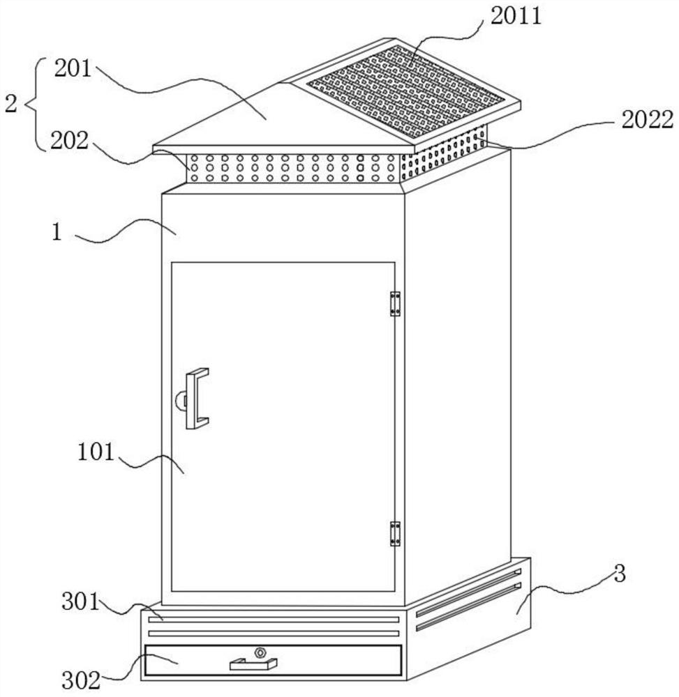
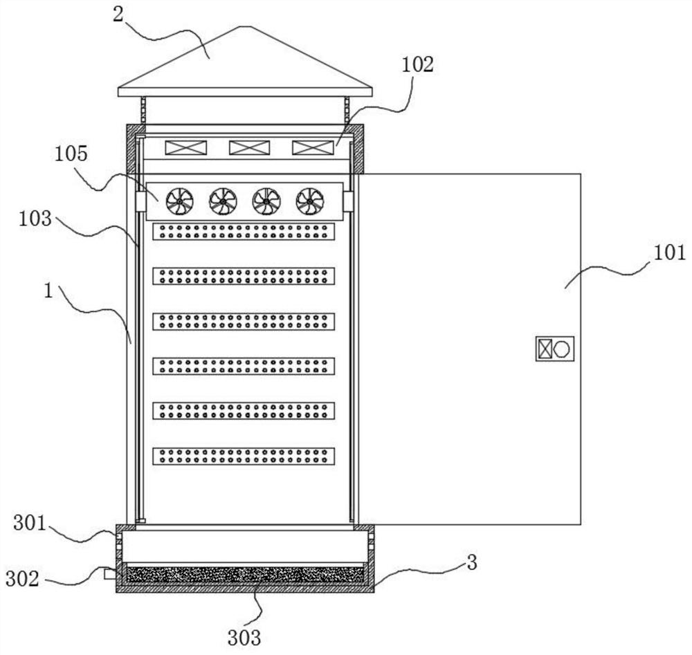
[0034] refer to Figure 1-7 , this embodiment includes a cabinet body 1, a rainproof ceiling 2 and a moisture-proof base 3, the rainproof ceiling 2 and the moisture-proof base 3 are fixedly arranged on the top and bottom of the cabinet body 1 respectively, and the three are connected to each other, and the rainproof ceiling 2 is arranged There are air intake holes 2022;
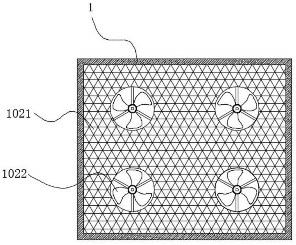
[0035] The top of the cabinet body 1 inner cavity is equipped with a longitudinal cooling mechanism 102, and the cabinet body 1 is located on both sides of the cabinet door 101. Guide rails 103 are installed longitudinally on the inner walls of both sides of the cabinet body 101, and a mobile cooling mechanism 105 is installed between the two guiding rails 103. The heat dissipation mechanism 105 is driven by the drive mechanism 104 to move up and down along the cabinet body 1 to dissipate heat;
[0036] The side wall of the upper half of the moisture-proof base 3 is provided with a heat dissipation window 30...
Embodiment 2
[0048] refer to Figure 1-6 and 8. The difference between this embodiment and Embodiment 1 is that the structure of the mobile cooling mechanism 105 is different. In this embodiment, a rotating groove 1056 is opened in the middle of the moving bracket 1051, and a rotating plate 1057 is installed in the rotating groove 1056 through the rotation of the rotating shaft. , the moving blower fan 1052 is installed on the rotating plate 1057, and the rotating plate 1057 is driven by a motor 1058 installed on the moving bracket 1051.
[0049] In this embodiment, the mobile fan 1052 is installed on the rotating plate 1057, and the motor 1058 drives the mobile fan 1052 on the rotating plate 1057 to swing. When the mobile cooling mechanism 105 moves up and down, the mobile fan 1052 can swing at a certain angle. Dust is blown from multiple angles, which further improves the dust removal effect on the surface of electrical components.
Embodiment 3
[0051] refer to Figure 4 In this embodiment, multiple sets of temperature sensors 106 are added, and multiple sets of temperature sensors 106 are installed equidistantly from top to bottom on the inner wall of the cabinet body 1 .
[0052] In this embodiment, the temperature sensor 106 can monitor the temperature of each position of the inner cavity of the cabinet body 1 in real time in different regions. The efficiency of heat dissipation is greatly improved, and precise and rapid heat dissipation is realized.
PUM
 Abstract
Description
Claims
Application Information
 - Generate Ideas
- Intellectual Property
- Life Sciences
- Materials
- Tech Scout
- Unparalleled Data Quality
- Higher Quality Content
- 60% Fewer Hallucinations
Browse by: Latest US Patents, China's latest patents, Technical Efficacy Thesaurus, Application Domain, Technology Topic, Popular Technical Reports.
© 2025 PatSnap. All rights reserved.Legal|Privacy policy|Modern Slavery Act Transparency Statement|Sitemap|About US| Contact US: help@patsnap.com


