Eureka AIR delivers breakthrough ideas for toughest innovation challenges, trusted by R&D personnel around the world.

L-shaped steel plate visual inspection equipment with bending angle detection function

A bending angle and visual inspection technology, applied in the field of visual inspection, can solve the problems of inability to detect the bending angle of L-shaped steel plates, integrating into L-shaped steel plates, and cumbersome inspection process, so as to improve the accuracy and inspection efficiency, and achieve accurate inspection results. The effect of improving efficiency and accuracy

Inactive Publication Date: 2021-01-05
广州市金点子机电科技发展有限公司
View PDF0 Cites 3 Cited by
  • Summary
  • Abstract
  • Description
  • Claims
  • Application Information

AI Technical Summary

Problems solved by technology

[0004] Aiming at the deficiencies of the prior art, the present invention provides a visual detection device for L-shaped steel plates with a bending angle detection function, which solves the problem that the general visual detection equipment proposed in the above background technology cannot intuitively detect the bending angle of the L-shaped steel plate , and cannot be well integrated into the production and processing process of L-shaped steel plates, the detection process is relatively cumbersome, and the products need to be sorted manually in the later stage

Method used


Image

  • L-shaped steel plate visual inspection equipment with bending angle detection function
  • L-shaped steel plate visual inspection equipment with bending angle detection function
  • L-shaped steel plate visual inspection equipment with bending angle detection function

Examples


Embodiment Construction

[0031] The technical solutions in the embodiments of the present invention will be clearly and completely described below in conjunction with the accompanying drawings in the embodiments of the present invention. Obviously, the described embodiments are only some of the embodiments of the present invention, not all of them. Based on The embodiments of the present invention and all other embodiments obtained by persons of ordinary skill in the art without making creative efforts belong to the protection scope of the present invention.

[0032] In the description of the present invention, unless otherwise stated, the meaning of "plurality" is two or more; the terms "upper", "lower", "left", "right", "inner", "outer" , "front end", "rear end", "head", "tail", etc. indicate the orientation or positional relationship based on the orientation or positional relationship shown in the drawings, and are only for the convenience of describing the present invention and simplifying the desc...


PUM


Abstract

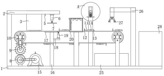
The invention discloses L-shaped steel plate visual inspection equipment with a bending angle detection function. The equipment comprises a bottom plate and a cross arm, wherein the cross arm is arranged at the upper left end of the bottom plate; T-shaped holes are arranged in the left side and the right side of a storage bin; a lifting rod is arranged at the right side of an inductor; a half gearis arranged above the left part of the bottom plate; a conveyor belt is arranged above a full gear; a pushing block is arranged at the left end of a flat plate; a push rod is arranged in front of a clamping block; a first motor is arranged at the right side of the half gear; a supporting plate is arranged at the top end of a stand column; a hydraulic rod is arranged above a cantilever; a shell isarranged on the periphery of a visual detector; a detector is arranged above a rotating plate; a slide rail is arranged at the right side of a first light sensor. Compared with existing visual inspection equipment, the L-shaped steel plate visual inspection equipment with the bending angle detection function has the advantages that the bending angle of an L-shaped steel plate can be visually detected, the detection process is simplified, and the L-shaped steel plate visual inspection equipment with the bending angle detection function is well integrated into machining and production procedures of plates.

Description

technical field [0001] The invention relates to the technical field of visual inspection, in particular to an L-shaped steel plate visual inspection device with a bending angle detection function. Background technique [0002] In recent years, many companies have begun to use visual inspection equipment in response to the trend of industrial development and the increase in labor costs. From a long-term perspective, it will help companies reduce unnecessary expenditures. the only way. [0003] The existing visual inspection equipment cannot intuitively detect the bending angle of the L-shaped steel plate, and cannot be well integrated into the production and processing process of the L-shaped steel plate. The detection process is cumbersome, and the products need to be manually sorted later. , therefore, we provide a visual detection equipment for L-shaped steel plate with bending angle detection function. Contents of the invention [0004] Aiming at the deficiencies of t...

Claims


Application Information

Patent Timeline
IPC IPC(8): B07C5/10B07C5/02B07C5/36B23D19/00
CPCB07C5/02B07C5/10B07C5/362B23D19/00
Inventor 覃海莲王燕王国旭
Owner 广州市金点子机电科技发展有限公司
Why Eureka
Eureka Blog
Learn More