A CNC Machining Method for Controlling Machining Deformation of Large Aluminum Alloy Wall Panel Parts

A technology of part processing and processing method, which is applied in the field of numerical control processing to control the processing and deformation of large aluminum alloy wall plate parts, and can solve the problems of no distinction between the initial deformation of the blank, the difficulty of processing large warpage deformation, and the low efficiency of roll forming. , to achieve the effect of reducing machining allowance, reducing machining difficulty and improving rolling efficiency

Active Publication Date: 2022-01-25
CHENGDU AIRCRAFT INDUSTRY GROUP
View PDF7 Cites 0 Cited by
  • Summary
  • Abstract
  • Description
  • Claims
  • Application Information

AI Technical Summary

Problems solved by technology

The large amount of warping deformation brings greater processing difficulty to the subsequent roll forming of the wall plate parts, which makes the roll forming efficiency low and the overall processing cycle of the parts increases
[0003] Due to the structural characteristics of one side smooth surface and one side frame surface, the wall panel parts, such as figure 1 , figure 2 As shown, the amount of material removal on the frame surface is much larger than that on the smooth surface, resulting in warpage and deformation of the part after processing to the side where more material is removed, that is, the frame surface
The blanks of wall panel parts are large-sized thin sheets. Due to the large size in the length and width directions and too thin thickness, the blank sheet itself has certain warping deformation, such as image 3 As shown, the existing processing methods do not distinguish the initial deformation of the blank, which also has a certain impact on the final deformation of the part after NC machining
[0004] In the existing numerical control machining of aluminum alloy wall plate parts, the problem of excessive deformation of the parts after processing is rarely considered, and it often relies on subsequent roll forming, which has caused great trouble to the roll bending process.

Method used


Image

  • A CNC Machining Method for Controlling Machining Deformation of Large Aluminum Alloy Wall Panel Parts
  • A CNC Machining Method for Controlling Machining Deformation of Large Aluminum Alloy Wall Panel Parts
  • A CNC Machining Method for Controlling Machining Deformation of Large Aluminum Alloy Wall Panel Parts

Examples


Embodiment 1

[0033] This embodiment provides a numerical control machining method for controlling machining deformation of large aluminum alloy wall panel parts, which specifically includes the following steps:

[0034] (1) Before processing, measure the deformation of the part blank to determine the concave and convex surfaces of the part blank;

[0035] (2) Repair the concave surface of the part blank, so that the concave surface of the part blank has a slight rebound, and use the concave surface of the part blank as the smooth surface of the large aluminum alloy wall panel part;

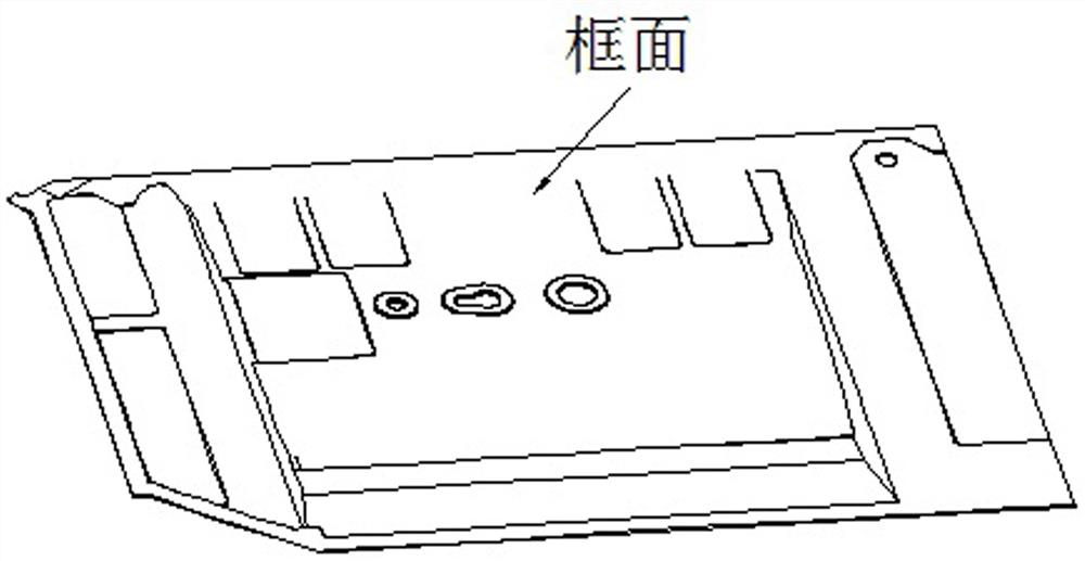
[0036] (3) Use the convex surface of the part blank as the frame surface of the large aluminum alloy siding part, and then process it to form the frame of the convex surface of the part blank, thereby obtaining a large aluminum alloy siding part with greatly improved deformation.

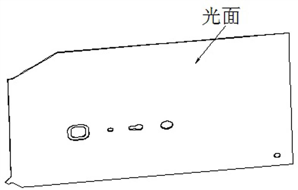
[0037] The specific implementation process, such as Figure 4 As shown, the concave surface (A surface) is selected as the smooth...

Embodiment 2

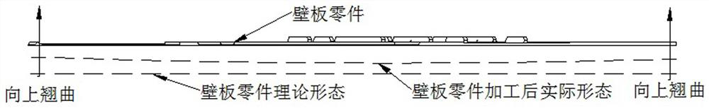
[0039] On the basis of the above-mentioned embodiments, this embodiment further defines that in the step (2), before trimming the concave surface of the part blank, it is necessary to allocate the machining allowance of the smooth surface and the frame surface of the part blank, Such as Figure 5 As shown, under the premise of satisfying the processing, increase the machining allowance of the smooth surface of the part blank, and reduce the machining allowance of the frame surface of the part blank.

[0040] When distributing the machining allowance on both sides, under the premise of satisfying the processing, increase the smooth surface machining allowance D1, reduce the frame surface machining allowance D2, make the smooth surface machining allowance D1 larger than the frame surface D2, and reduce the material removal amount on both sides The gap between them, thereby reducing the warping deformation of the parts to the frame surface after processing. Other parts of this e...

Embodiment 3

[0042] On the basis of the above-mentioned embodiments, this embodiment further defines that in the step (3), before machining the convex surface of the part blank into a frame surface, it is necessary to process a plurality of interlaced stress relief grooves on the convex surface of the part blank. Such as Figure 6 As shown, when roughing the frame surface of the part. At the beginning of rough machining, multiple interlaced stress relief grooves are processed on the frame surface to release the residual stress of the blank. Other parts of this embodiment are the same as those of the foregoing embodiment, and will not be repeated here.


PUM


Abstract

The invention discloses a numerical control processing method for controlling the processing deformation of large aluminum alloy wall plate parts, which comprises the following steps: 1) before processing, measuring the deformation of the part blank to determine the concave surface and the convex surface of the part blank; The concave surface of the part blank is used for trimming, so that the concave surface of the part blank has a slight rebound, and the concave surface of the part blank is used as the smooth surface of the large aluminum alloy siding part; 3) The convex surface of the part blank is used as the large aluminum alloy siding part The frame surface is then processed to form the frame of the convex surface of the part blank to obtain large aluminum alloy siding parts. The invention uses the deformation of the blank itself to offset the deformation of some parts after processing, and reduces the gap between the material removal amount between the smooth surface and the frame surface, thereby reducing the warping deformation of the parts to the frame surface after processing, and reducing the subsequent rolling deformation. The difficulty of bending and forming can improve the efficiency of rolling and bending, and shorten the manufacturing cycle of large wall plate parts, which is suitable for wide application.

Description

technical field [0001] The invention relates to the technical field of aluminum alloy cutting and processing, in particular to a numerical control processing method for controlling the processing deformation of large aluminum alloy wall plate parts. Background technique [0002] Aluminum alloy siding parts are an important aircraft structural part. Its typical structural form is smooth on one side and framed on the other. The parts have large dimensions in the length and width directions and small dimensions in the thickness direction. With the improvement of aircraft performance, wall panel parts are developing in the direction of large-scale and high-precision, which brings about an increase in the difficulty of CNC machining. Under the existing CNC machining method, the clamping scheme of the wall panel parts adopts the clamping method of vacuum adsorption tooling as the main tooling, and the pressing plate as the supplementary clamping method. Surface finishing, smooth ...

Claims


Application Information

Patent Timeline
Patent Type & Authority Patents(China)
IPC IPC(8): B23P15/00
CPCB23P15/00
Inventor 牛印杜晓文翟立恒张超海李天栋廖双权王灿
Owner CHENGDU AIRCRAFT INDUSTRY GROUP
Why Eureka
Try Eureka