
Efficient membrane humidifier for fuel cell

A high-efficiency membrane humidifier, fuel cell technology, applied in fuel cells, electrochemical generators, circuits, etc., can solve the problems of large deterioration, deterioration of velocity distribution, increase of dry airflow field flow resistance, etc., and achieve mass transfer coefficient and Optimized drag coefficient, improved flow distribution uniformity, reduced impact and separation effects

Pending Publication Date: 2020-12-18
天朤(江苏)氢能源科技有限公司
View PDF0 Cites 0 Cited by
  • Summary
  • Abstract
  • Description
  • Claims
  • Application Information

AI Technical Summary

Problems solved by technology

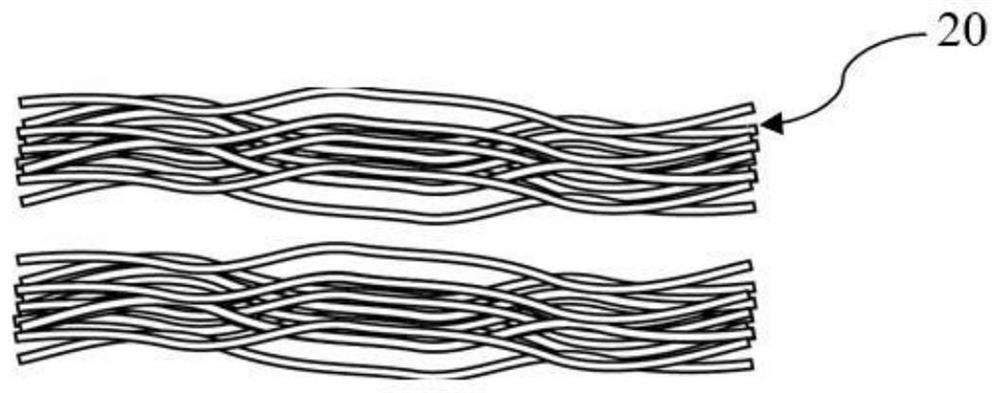
[0004] in, figure 1 It is randomly placed in the same direction. In this form, since the humidifying membrane tube 20 is soft, the state of the humidifying membrane tube 20 in the humidification module is bent and in a loose state, and bending will increase the flow resistance of the dry air field , and will cause the vibration of the humidifying membrane tube 20 due to the Coanda effect, which will increase the flow resistance and affect the service life of the humidifying membrane tube 20; the randomness of the random distribution of the tube bundle will seriously deteriorate the velocity distribution of the external flow field of the tube bundle , this non-uniform flow distribution makes the random arrangement of the tube bundles lead to a significant decrease in the heat and mass transfer performance, and the conjugate boundary on the membrane surface of the humidifying membrane tube 20 makes this worse effect, and the corresponding convective heat and mass transfer coefficient Lower than that under ideal boundary conditions; the filling rate of the integrated membrane tube of the whole humidifier is lower, which affects the humidification efficiency;
[0005] in, figure 2 It is bundled into bundles and randomly placed in the same direction. In this form, since the humidifying membrane tubes 20 are relatively soft, even if bundled into bundles, although the transverse bending has been improved, there are still disadvantages of random placement; bundled tube bundles The humidifying membrane tubes 20 in the humidifier are still randomly placed, and the velocity distribution of the external flow field is still seriously deteriorated; the filling rate of the integrated membrane tubes of the entire humidifier is low, which affects the humidification efficiency;
[0006] in, image 3 It is first integrated into a cage-type humidification unit, and then single or multiple are arranged in the shell. In this form, the state of the humidification membrane tubes 20 in the integrated cage 3 is equivalent to a larger bundle of bundled tubes after being more tightly bundled. Although the humidification membrane tubes 20 are arranged horizontally more straightly, the humidifying membrane tubes 20 in the integrated cage 3 are closer to each other, and its shock resistance performance is improved, but there is still the problem of random placement of the humidifying membrane tubes 20; the tighter humidifying membrane tubes 20 make It is difficult for the humidifying medium to enter the inside of the tube bundle, which leads to too small local velocity inside the component or the appearance of a flow dead zone, and the uneven flow distribution still has a deteriorating effect on the cooling efficiency and humidification efficiency of the component; in order to reduce the flow resistance of the humidifying medium, in the humidification unit Sufficient space must be left when placed in the housing, which affects the composite membrane tube fill rate

Method used


Image

  • Efficient membrane humidifier for fuel cell
  • Efficient membrane humidifier for fuel cell
  • Efficient membrane humidifier for fuel cell

Examples


Embodiment Construction

[0037] The technical solutions in the embodiments of the present invention will be clearly and completely described below in conjunction with the embodiments of the present invention. Apparently, the described embodiments are only some of the embodiments of the present invention, not all of them. Based on the embodiments of the present invention, all other embodiments obtained by persons of ordinary skill in the art without making creative efforts belong to the protection scope of the present invention.

[0038] The technical solutions of the present invention are described in detail below using examples.

[0039] Such as Figure 4-9 As shown, this embodiment provides a fuel cell high-efficiency membrane humidifier, which at least includes a housing 1, the housing 1 is a three-dimensional structure, and the two sides of the three-dimensional structure of the housing 1 are provided with opposite humidification medium inlets and outlets. The inside of the cavity on both sides o...


PUM


Abstract

The invention discloses a fuel cell efficient membrane humidifier which at least comprises a shell, opposite humidifying medium inlets and outlets are formed in the two sides of the shell, a flow guide cavity is formed in the shell, and the humidifying medium inlets and outlets are communicated with the flow guide cavity; a membrane humidifying assembly is arranged between the flow guide cavitiesin the two sides of the interior of the shell and is at least provided with humidifying membrane pipes arranged in a square matrix mode; connecting flow guide end covers are arranged on the two sides,adjacent to the inlet and outlet, of the shell, and the flow guide end covers on the two sides communicate with air guide openings. By means of the structure, the impact and separation effect betweenpipe bundles of the humidification film pipe can be effectively reduced, disturbance in a flow field is reduced, and the flow distribution uniformity of humidification media on the outer side of thehumidification film pipe is improved; the air flow in the humidifying membrane tube is smoother, the membrane tube is prevented from vibrating, the resistance in the membrane tube is reduced, and theservice life of the membrane tube is prolonged; in addition, the uniform gaps formed in the longitudinal direction of the humidifying film pipe increase the filling rate of the film pipe and meanwhiledo not increase resistance, and therefore the mass and heat transfer efficiency of the whole humidifier is improved.

Description

technical field [0001] The invention relates to the field of proton exchange membrane fuel cell systems, in particular to a fuel cell high-efficiency membrane humidifier. Background technique [0002] Proton exchange membrane fuel cell (PEMFC) has the advantages of environmental protection, high efficiency, fast start-up speed, and high power density. It is one of the main competitors in the future transportation power system. work performance. Both fuel cell air and hydrogen intake need to be humidified to prevent dehydration of the proton exchange membrane from reducing battery performance and working life, so that the fuel cell can work efficiently. Among many humidification technology routes, the wet exhaust gas placed in PEMFC is recycled by the membrane humidifier to humidify and heat the reactants, because it has the advantages of stable humidification, strong controllability, large humidification capacity, and no additional power consumption. It has become the curr...

Claims


Application Information

Patent Timeline
IPC IPC(8): H01M8/04119H01M8/1007
CPCH01M8/04149H01M2008/1095H01M8/1007Y02E60/50
Inventor 杨田明
Owner 天朤(江苏)氢能源科技有限公司
Learn More