
Manufacturing method of roll-bond aluminum vapor chamber

A production method and a technology of a uniform temperature plate, which is applied in the direction of cooling/ventilation/heating transformation, electrical components, and electrical equipment structural parts, etc., can solve the problems of inability to meet the heat dissipation requirements of base stations and poor heat dissipation efficiency, and achieve improved production efficiency and good quality. efficiency, overcome difficulties, and improve production efficiency

Pending Publication Date: 2020-12-15
DONGGUAN LINGJIE PRECISION MACHINING TECH CO LTD
View PDF6 Cites 2 Cited by
  • Summary
  • Abstract
  • Description
  • Claims
  • Application Information

AI Technical Summary

Problems solved by technology

[0002] Traditional base station radio frequency amplifier chip heat dissipation adopts a heat dissipation module made of die-cast aluminum shell embedded with aluminum heat dissipation fins. The heat dissipation can only be carried out through the heat conduction ability of aluminum, and the heat dissipation efficiency is poor.
With the application of 5G, the power of communication base stations does not increase, and the use of traditional base station heat dissipation can no longer meet the heat dissipation requirements of base stations

Method used


Image

  • Manufacturing method of roll-bond aluminum vapor chamber
  • Manufacturing method of roll-bond aluminum vapor chamber
  • Manufacturing method of roll-bond aluminum vapor chamber

Examples


Embodiment 1

[0024] figure 1 A schematic flow diagram schematically showing a method for manufacturing an inflated aluminum vapor chamber according to an embodiment of the present invention. The specific steps are as follows:

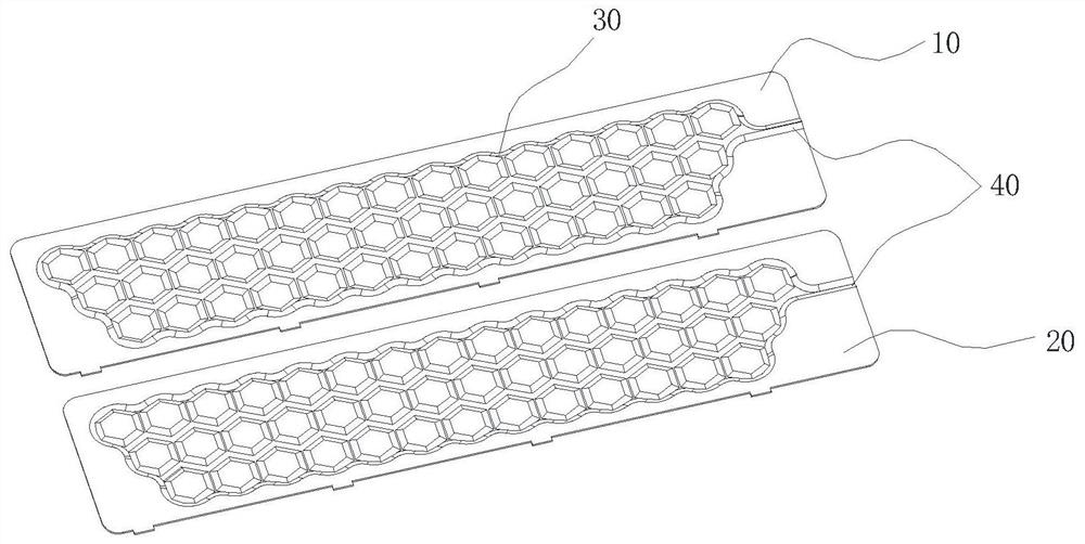
[0025] S1. Select the main body of the aluminum inflation plate. The main body of the inflation plate includes a heat sink 1 and an inlet 40 . Wherein the heat sink 1 is formed by corresponding covering of the upper cover plate 10 and the lower cover plate 20, the edges of the upper cover plate 10 and the lower cover plate 20 are welded and sealed to form the main structure of the heat sink 1, the upper cover plate 10, the lower cover plate 20 jointly define a flow channel 30 ; the inlet 40 corresponds to one end of the heat sink 1 and communicates with the flow channel 30 . The thickness of the upper cover plate 10 and the lower cover plate 20 is no more than 1.5 mm, and the thickness of the main body of the inflation plate is 5 mm. The structure of the main body...

Embodiment 2

[0032] The difference between this embodiment and embodiment 1 is:

[0033] The main body of the expansion plate is made of aluminum alloy, which is hard and easy to process, which can ensure the product quality of the aluminum vapor chamber;

[0034] The thickness of the main body of the inflation plate is 4.5 mm, and the thickness of the upper cover plate 10 and the lower cover plate 20 is not more than 1.2 mm;

[0035] The working fluid is Honeywell 1233ZD, a fluorinated liquid, which is gaseous at normal temperature and pressure, and has a boiling point of 18°C. In step 3, the tank body does not need to be heated, and the working fluid can be perfused; Cool the main body of the blown plate to below 15°C to ensure that the Honeywell 1233ZD is fully liquefied. During this process, the range of temperature change is small, which can reduce energy consumption. In addition, the working medium can be replaced by fluorinated liquids such as R134A, R22, 3M 7100, etc. Similar to...


PUM

PropertyMeasurementUnit
thicknessaaaaaaaaaa

Abstract

The invention discloses a manufacturing method of a roll-bond aluminum vapor chamber. The method comprises the following steps of vacuumizing a roll-bond plate main body, injecting a working medium into a runner in the aluminum roll-bond plate in a gaseous state, cooling the roll-bond plate main body, condensing the working medium steam injected into the roll-bond plate into a liquid state, and carrying out seal welding to manufacture the aluminum vapor chamber. According to the method, the liquid injection amount of the working medium can be controlled in a scenic spot, so consistency of thevapor chamber is ensured, and the product performance reaches the optimal level. The method plays a very important role in improving the heat dissipation capacity of the vapor chamber, reducing thickness and improving the yield stability.

Description

technical field [0001] The invention relates to the technical fields of gravity heat pipes, vapor chambers and radiators, in particular to a manufacturing method of an inflatable aluminum vapor chamber. Background technique [0002] Traditional base station radio frequency amplifier chip heat dissipation adopts a heat dissipation module made of die-cast aluminum shell embedded with aluminum heat dissipation fins. The heat dissipation can only be carried out through the heat conduction ability of aluminum itself, and the heat dissipation efficiency is poor. With the application of 5G, the power of communication base stations does not increase, and the use of traditional base station heat dissipation can no longer meet the heat dissipation requirements of base stations. [0003] Aluminum vapor chamber is a device that completes heat absorption and transfer through the conversion of working fluid gas phase and liquid phase. Maintenance, no noise and other advantages, is a recy...

Claims


Application Information

Patent Timeline
Patent Type & Authority Applications(China)
IPC IPC(8): H05K7/20B23P15/26
CPCH05K7/20336B23P15/26
Inventor 罗合云梁平平李学华
Owner DONGGUAN LINGJIE PRECISION MACHINING TECH CO LTD
Learn More