
Device and method for preparing glow discharge sputtering sample for microscopic characterization of material

A glow discharge and sample preparation technology, applied in the preparation of test samples, electron/ion optical devices, discharge tubes, etc., can solve the problems of changing organizational structure, small area, high cost, etc., and achieve uniform sample sputtering and distribution Equalize, increase the effect of the motion path

Pending Publication Date: 2020-12-11
NCS TESTING TECH
View PDF1 Cites 2 Cited by
  • Summary
  • Abstract
  • Description
  • Claims
  • Application Information

AI Technical Summary

Problems solved by technology

At the same time, this existing technology uses radio frequency glow discharge mass spectrometer for analysis and detection, instead of using glow discharge technology for sample preparation to achieve layer-by-layer erosion of material microstructure
[0006] At present, the most commonly used method for exfoliating the microstructure of materials layer by layer is the focused ion beam (FIB) technology, which can realize micromachining in the range of tens of μm, and the processing accuracy is less than 5nm, but there are also small areas, There are many shortcomings such as changing the organizational structure of the amorphous layer, long time (several hours), high cost, etc.

Method used


Image

  • Device and method for preparing glow discharge sputtering sample for microscopic characterization of material
  • Device and method for preparing glow discharge sputtering sample for microscopic characterization of material
  • Device and method for preparing glow discharge sputtering sample for microscopic characterization of material

Examples


Embodiment

[0090] The device for preparing samples by glow discharge sputtering for material microscopic characterization of the present invention is used to prepare large-scale samples of nickel-based single crystal superalloy samples. The operation steps are as follows:

[0091] Sample preparation: cut the sample into a size not less than 20mm, which can completely cover the anode cylinder of the glow discharge sputtering device and the sealing O-ring on the cathode disk. If the sample is too small, it needs to be hot-mounted with conductive resin to ensure that the sample It can be sputtered normally; the cut sample is ground and polished in sequence to obtain a flat and clean sample surface, which is ready for use.

[0092] The prepared sample can be marked with a microhardness tester, such as Figure 8 As shown, the width of the marking point is about 30 μm, and the coordinates of each marking point can be accurately obtained when the hardness point is punched by a microhardness te...


PUM

PropertyMeasurementUnit
Diameteraaaaaaaaaa
Widthaaaaaaaaaa

Abstract

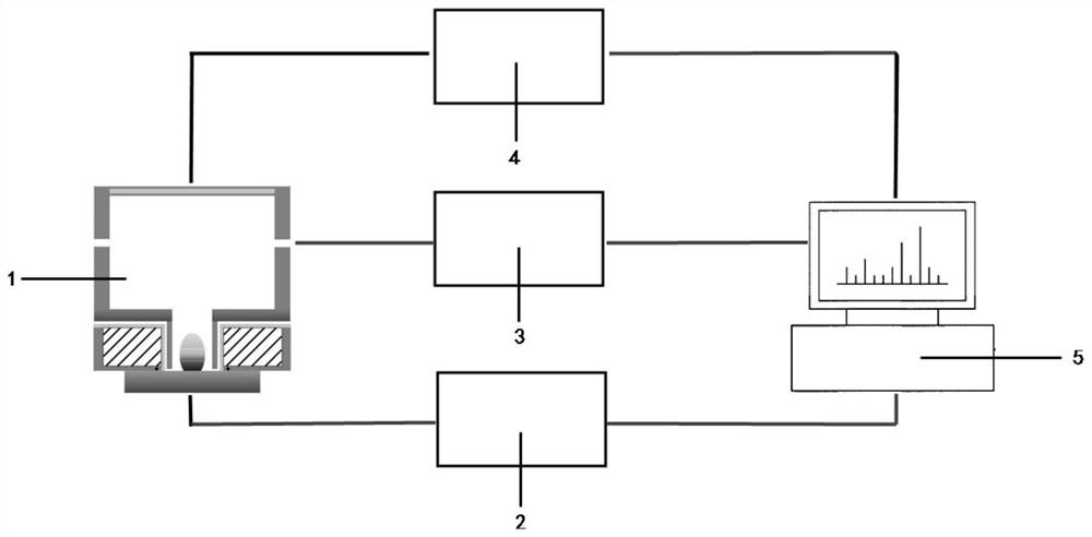
The invention relates to a device and a method for preparing a glow discharge sputtering sample for microscopic characterization of a material. The device comprises a glow discharge sputtering unit, aglow discharge energy supply source, an automatic gas circuit control unit, a spectrograph and a computer, wherein a glow discharge sputtering unit structure is more suitable for sample preparation through simulation optimization, and uniform sample sputtering on the surface of a sample in a large-size range is realized by applying a magnetic field to glow plasma; and the spectrograph is used formonitoring element spectral signals in the sputtering depth direction of the sample so as to realize accurate preparation of tissue structures of different layers. By combining the sample position mark and the acquisition of accurate space coordinate (x, y, z) information, the correspondence between the space coordinate of the sample preparation surface and the tissue structure is realized. Thus,large-size flat preparation of the sample at the millimeter-cm level can be achieved, no damage is caused to the material tissue structure, layer-by-layer preparation can be conducted in the depth direction of the surface of the sample, preparation is rapid, and the cost is low.

Description

technical field [0001] The invention belongs to the technical field of material analysis and characterization, and relates to a device and method for preparing glow discharge sputtering samples for material microscopic characterization. Background technique [0002] The current sample preparation techniques used for material microstructure characterization, such as mechanical polishing, electrolytic polishing, and focused ion beam (FIB), have the disadvantages of long time consumption, damage to the sample surface, difficult control of polishing conditions, small sample preparation area, and high cost. High-level shortcomings, can not fully meet the needs of large-scale, overall, real information acquisition of the sample microstructure. [0003] Glow discharge belongs to a kind of low-pressure gas discharge, as an effective atomization and excitation light source, it is mostly used for elemental analysis of solid materials. The sample atoms are stripped layer by layer from...

Claims


Application Information

Patent Timeline
IPC IPC(8): G01N1/28H01J37/32
CPCG01N1/28H01J37/32018G01N21/67C23C14/3435H01J49/0459H01J49/06H01J49/12
Inventor 余兴王海舟沈学静李小佳朱一妃万卫浩卢毓华王辉任群王永清万真真
Owner NCS TESTING TECH
Learn More