
Braking system for new energy vehicle and control method of braking system

A technology for a new energy vehicle and a braking system, which is applied to the braking system of a new energy vehicle and its control field, can solve the problems of safety failure and high probability of system failure, and achieves improved safety, improved vehicle safety, development and verification. short cycle effect

Active Publication Date: 2020-12-11
ZHEJIANG GEELY NEW ENERGY COMML VEHICLES CO LTD +3
View PDF16 Cites 0 Cited by
  • Summary
  • Abstract
  • Description
  • Claims
  • Application Information

AI Technical Summary

Problems solved by technology

[0004] However, for new energy medium and heavy-duty trucks and passenger cars (and some new energy light trucks) that use air brake systems, as well as other new energy models that use air brake systems, since their brake systems use a single Energy supply device, from the perspective of system functional safety, its system failure probability is relatively high, so there is a hidden danger of safety failure

Method used


Image

  • Braking system for new energy vehicle and control method of braking system
  • Braking system for new energy vehicle and control method of braking system
  • Braking system for new energy vehicle and control method of braking system

Examples


Embodiment Construction

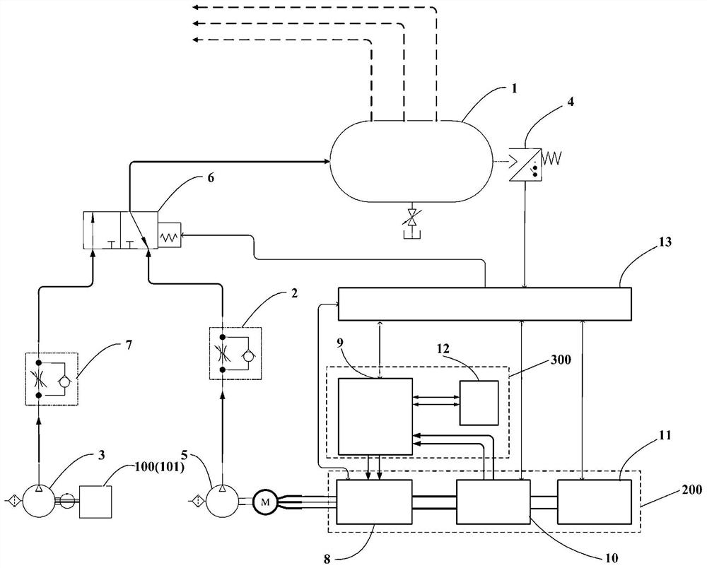
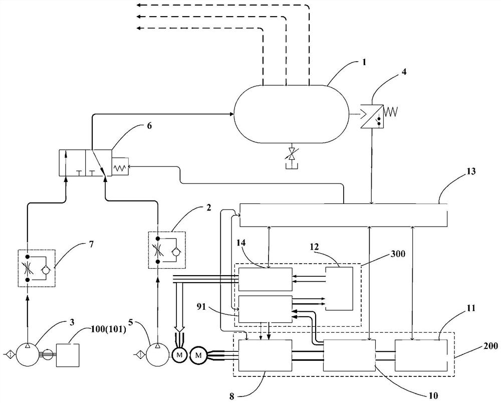
[0052] At present, the power source of the energy supply device of the air pressure braking system of the traditional fuel vehicle comes from the engine. The engine drives the air compressor to provide energy for the braking system through a mechanical coupling mechanism, and then intermittently inflates and maintains the pressure of the system’s air storage tank device, which is for the system. The braking system provides safe brake air pressure. The pneumatic transmission device transmits the brake air pressure to each actuator according to the driver's braking request, and finally applies the corresponding braking force to the wheels of the whole vehicle (including towed vehicles) through energy conversion. At present, the power source of the energy supply device of the pneumatic brake system of new energy vehicles is different from that of traditional fuel vehicles. Electric air compressors are mostly used to provide energy for the entire system, and other devices are the s...


PUM


Abstract

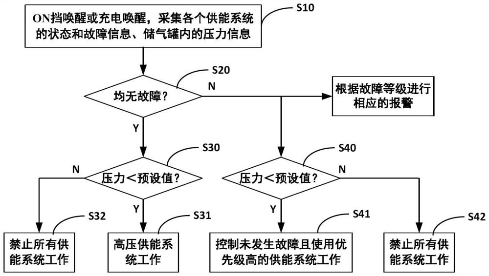
The invention provides a braking system for a new energy vehicle and a control method of the braking system, and belongs to the field of vehicle control. The braking system comprises an air storage tank, an air pressure sensor, an engine energy supply system, a high-voltage energy supply system, a low-voltage energy supply system, a mechanical air compressor, an electric air compressor and a vehicle control unit, wherein the air pressure sensor is connected with the air storage tank and used for monitoring the pressure in the air storage tank, the engine energy supply system, the high-voltageenergy supply system and the low-voltage energy supply system take an engine, a high-voltage battery system and a storage battery as power sources respectively, the mechanical air compressor is controllably driven by the engine, the electric air compressor is controllably driven by the high-pressure energy supply system or the low-pressure energy supply system, and the vehicle control unit is in signal connection with the air pressure sensor, a switching valve, the engine energy supply system, the high-pressure energy supply system and the low-pressure energy supply system, and is used for controlling the corresponding energy supply system to inflate the air storage tank according to the state and fault information of the engine energy supply system, the high-pressure energy supply systemand the low-pressure energy supply system and pressure information in the air storage tank. According to the braking system and the control mode thereof, the safety of the vehicle can be improved.

Description

technical field [0001] The invention belongs to the field of vehicle control, and in particular relates to a braking system for new energy vehicles and a control method thereof. Background technique [0002] The vacuum power source of the traditional fuel vehicle vacuum booster comes from the car engine, but the new energy vehicle, especially the pure electric vehicle, has no engine assembly and the braking system lacks a vacuum power source, so the electronic vacuum booster is also used. pregnancy. In order to meet the requirements of energy saving and environmental protection, new energy vehicles require the braking system to reduce the dependence on the vacuum of the engine, or even not to rely on the vacuum of the engine. Moreover, new energy vehicles require the braking system to be able to achieve active conventional braking with low noise. [0003] The requirements of new energy vehicles on the braking system are difficult or even impossible to achieve by traditiona...

Claims


Application Information

Patent Timeline
Patent Type & Authority Applications(China)
IPC IPC(8): B60T13/26B60T17/06B60T13/66B60T17/22
CPCB60T13/26B60T13/66B60T17/06B60T17/22
Inventor 卢锦龙王荣华郝永健
Owner ZHEJIANG GEELY NEW ENERGY COMML VEHICLES CO LTD
Learn More