


Quick Research
Generate reliable direction feasibility study reports for your R&D in just a few steps.

Technical Q&A
Discover and master advanced knowledge NOW. Basics, ideas, possibilities, all at once.

Find Solutions
As an expert in R&D theories, this can generate solutions to your technical problems instantly.

Evaluate Feasibility
Analyze your overall solution with one click, know your potential R&D risks in advance.

Monitor Landscape
Get weekly tech updates, stay abreast of the latest tech innovations and key insights.
A cladding processing method and system for an ultrafine single crystal optical fiber
An optical fiber cladding and processing method technology, applied in cladding optical fibers, microstructured optical fibers, metal processing equipment, etc., can solve problems such as poor repeatability, poor accuracy, and complex process routes
- Summary
- Abstract
- Description
- Claims
- Application Information
AI Technical Summary
Problems solved by technology
Method used
Image

Examples
Embodiment 1
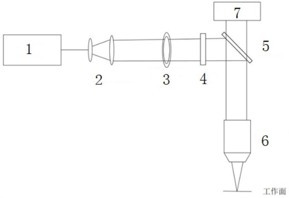
[0137] The laser processing system adopted in the first embodiment is as follows: figure 1 As shown, it mainly includes a laser 1 and a variable magnification beam expander 2, a variable annular diaphragm 3, a spatial light modulator 4, a mirror 5 and a focusing microscope objective lens 6, which are sequentially arranged in the laser output optical path, and also includes a laser Ranging\autofocus device7.
[0138] The outgoing laser light of the laser 1, after being expanded and collimated by the zoom beam expander 2, enters the SLM spatial light modulator 4 through the variable annular diaphragm 3, and the SLM spatial light modulator 4 adjusts the laser light into a Bessel beam, and passes through The variable annular diaphragm 3 flexibly cuts the Bessel beam online to a certain extent, reflects it to the focusing microscope objective lens 6 through the mirror 5, and focuses the processing beam to the working surface through the focusing microscope objective lens 6 to real...
Embodiment 2
[0167] The laser processing system adopted in the second embodiment is the same as that in the first embodiment, as figure 1 As shown, it mainly includes the laser and the variable magnification beam expander, variable annular diaphragm, spatial light modulator, reflector and focusing microscope objective lens arranged in sequence in the laser output optical path, and also includes the laser ranging\autofocus device .
[0168] The outgoing laser light of the laser, after adjusting the beam diameter through the variable beam expander, enters the SLM spatial light modulator through the variable annular diaphragm, and the SLM spatial light modulator adjusts the laser light into a Bessel beam, and then passes through the variable annular diaphragm The Bessel beam is cut flexibly online, reflected by the mirror to the focusing microscope objective, and the processing beam is focused to the working surface by the focusing microscope objective to realize processing.
[0169] This e...
Embodiment 3
[0196] The difference between the laser processing system used in the second embodiment and the first embodiment is that the laser processing system in this embodiment does not include a variable annular diaphragm and a spatial light modulator. It includes a laser, a variable magnification beam expander, a reflector, and a focusing microscope objective lens sequentially arranged in the exit light path of the laser, and also includes a laser distance measuring / auto-focusing device.
[0197] The output laser light of the laser is adjusted to the diameter of the beam by the variable magnification beam expander, and reflected by the mirror to the focusing microscopic objective lens, and the processing beam is focused to the working surface by the focusing microscopic objective lens to realize processing.
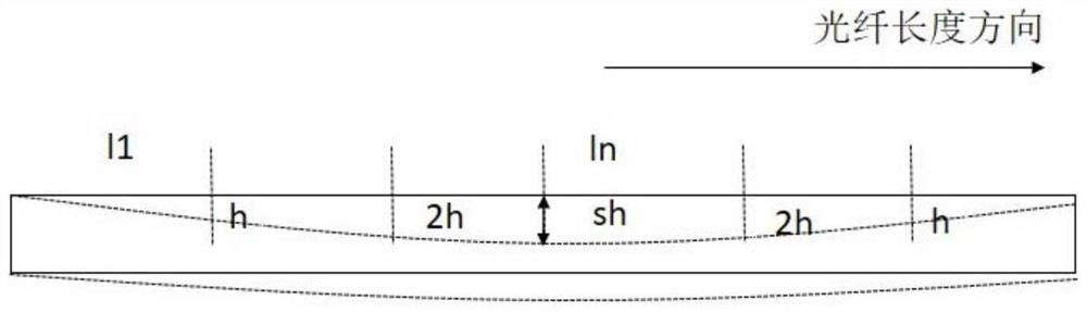
[0198] This embodiment is also suitable for regular deformation of the optical fiber, for example, the center of the optical fiber sinks due to the action of gravity, and the two...
PUM
 Abstract
Description
Claims
Application Information
 - R&D Engineer
- R&D Manager
- IP Professional
- Industry Leading Data Capabilities
- Powerful AI technology
- Patent DNA Extraction
Browse by: Latest US Patents, China's latest patents, Technical Efficacy Thesaurus, Application Domain, Technology Topic, Popular Technical Reports.
© 2024 PatSnap. All rights reserved.Legal|Privacy policy|Modern Slavery Act Transparency Statement|Sitemap|About US| Contact US: help@patsnap.com