
Method and system for processing superfine single crystal optical fiber cladding

A technology of optical fiber cladding and processing methods, which is applied in the direction of cladding optical fiber, microstructure optical fiber, metal processing equipment, etc., and can solve the problems of complex process route, poor repeatability, and low efficiency

Active Publication Date: 2020-12-11
XI'AN INST OF OPTICS & FINE MECHANICS - CHINESE ACAD OF SCI
View PDF6 Cites 4 Cited by
  • Summary
  • Abstract
  • Description
  • Claims
  • Application Information

AI Technical Summary

Problems solved by technology

[0006] Aiming at the problems of complex process route, low efficiency, poor repeatability and poor precision in the current method for preparing single crystal fiber cladding, the invention discloses a method for processing ultrafine single crystal fiber cladding

Method used


Image

  • Method and system for processing superfine single crystal optical fiber cladding
  • Method and system for processing superfine single crystal optical fiber cladding
  • Method and system for processing superfine single crystal optical fiber cladding

Examples


Embodiment 1

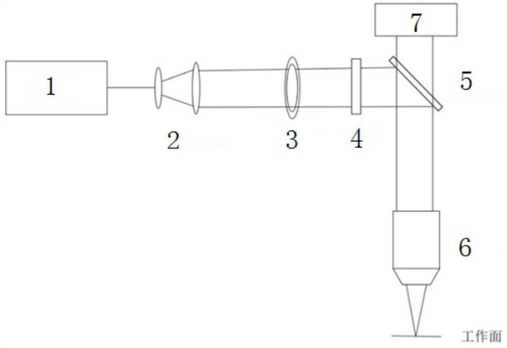
[0137] The laser processing system adopted in the first embodiment is as follows: figure 1 As shown, it mainly includes a laser 1 and a variable magnification beam expander 2, a variable annular diaphragm 3, a spatial light modulator 4, a mirror 5 and a focusing microscope objective lens 6, which are sequentially arranged in the laser output optical path, and also includes a laser Ranging\autofocus device7.

[0138] The outgoing laser light of the laser 1, after being expanded and collimated by the zoom beam expander 2, enters the SLM spatial light modulator 4 through the variable annular diaphragm 3, and the SLM spatial light modulator 4 adjusts the laser light into a Bessel beam, and passes through The variable annular diaphragm 3 flexibly cuts the Bessel beam online to a certain extent, reflects it to the focusing microscope objective lens 6 through the mirror 5, and focuses the processing beam to the working surface through the focusing microscope objective lens 6 to real...

Embodiment 2

[0167] The laser processing system adopted in the second embodiment is the same as that in the first embodiment, as figure 1 As shown, it mainly includes the laser and the variable magnification beam expander, variable annular diaphragm, spatial light modulator, reflector and focusing microscope objective lens arranged in sequence in the laser output optical path, and also includes the laser ranging\autofocus device .

[0168] The outgoing laser light of the laser, after adjusting the beam diameter through the variable beam expander, enters the SLM spatial light modulator through the variable annular diaphragm, and the SLM spatial light modulator adjusts the laser light into a Bessel beam, and then passes through the variable annular diaphragm The Bessel beam is cut flexibly online, reflected by the mirror to the focusing microscope objective, and the processing beam is focused to the working surface by the focusing microscope objective to realize processing.

[0169] This e...

Embodiment 3

[0196] The difference between the laser processing system used in the second embodiment and the first embodiment is that the laser processing system in this embodiment does not include a variable annular diaphragm and a spatial light modulator. It includes a laser, a variable magnification beam expander, a reflector, and a focusing microscope objective lens sequentially arranged in the exit light path of the laser, and also includes a laser distance measuring / auto-focusing device.

[0197] The output laser light of the laser is adjusted to the diameter of the beam by the variable magnification beam expander, and reflected by the mirror to the focusing microscopic objective lens, and the processing beam is focused to the working surface by the focusing microscopic objective lens to realize processing.

[0198] This embodiment is also suitable for regular deformation of the optical fiber, for example, the center of the optical fiber sinks due to the action of gravity, and the two...


PUM


Abstract

The invention relates to an optical fiber cladding processing method, in particular to a method and system for processing superfine single crystal optical fiber cladding. In order to solve the problems of complex process route, low efficiency, poor repeatability, poor precision and the like of the existing method for preparing the single crystal optical fiber cladding, the method comprises the following steps of: simulating to obtain the diameter and the depth of a microstructure; determining the theoretical focusing spot diameter of an optical system; shaping a laser beam into a Bessel beam;carrying out space cutting on the Bessel beam; determining a microstructure manufacturing focal depth h; segmenting an optical fiber; and adjusting the focal length, and processing the microstructureon the surface of the optical fiber; The system comprises a laser, and a zoom beam expander, a variable annular diaphragm, a spatial light modulator, a reflector and a focusing microscope objective which are sequentially arranged in an emergent light path of the laser, and further comprises a laser ranging\automatic focusing device. According to the method and system, the optical fiber is segmented, each segment corresponds to different focal lengths, the processing of each segment of the optical fiber is realized by adjusting the focal lengths on line, and the processing precision is high.

Description

technical field [0001] The invention relates to a method for processing the cladding of an optical fiber, in particular to a method for processing the cladding of an ultrafine single crystal optical fiber. Background technique [0002] The significance of the fiber cladding is that it can realize the total reflection of the light beam inside the fiber by reducing the refractive index outside the fiber and improve the efficiency of the optical waveguide. The glass fiber is prepared with a silica cladding that has a refractive index difference with the fiber core outside the fiber, which can achieve total reflection and obtain a high-efficiency optical waveguide. However, single crystal optical fiber is a new type of one-dimensional functional crystal material. It has the characteristics of high aspect ratio and large specific surface area of ​​glass optical fiber, and has the advantages of good heat dissipation, high efficiency, and simple thermal management. Although the tr...

Claims


Application Information

Patent Timeline
Patent Type & Authority Applications(China)
IPC IPC(8): B23K26/00B23K26/06B23K26/064B23K26/352B23K26/402G02B6/02
CPCB23K26/0006B23K26/0665B23K26/402B23K26/064B23K26/355G02B6/02295
Inventor 李明李珣刘红军李晨晨
Owner XI'AN INST OF OPTICS & FINE MECHANICS - CHINESE ACAD OF SCI
Learn More