An adjustable punching and folding processing machine for cable tray

A technology of a cable tray and an integrated machine is applied in the field of an adjustable cable tray punching, folding and processing integrated machine, which can solve the problems of low processing efficiency and increase personnel burden, and achieve the effect of ensuring stability.

Active Publication Date: 2022-03-25
江苏中顺电气有限公司
View PDF8 Cites 1 Cited by
  • Summary
  • Abstract
  • Description
  • Claims
  • Application Information

AI Technical Summary

Problems solved by technology

[0002] The rigid structural system with close support cables composed of trough-type, tray-type or step-type straight sections, bends, tees, four-way components, brackets, hangers, etc. is called a cable bridge. The cable bridge is divided into trough type, Tray-type, ladder-type, grid-type and other structures are composed of brackets, supporting arms and installation accessories. The bridges in buildings can be erected independently or attached to various buildings and pipe gallery supports. It should reflect the simple structure. Beautiful appearance, flexible configuration and convenient maintenance. All parts need to be galvanized. If the bridge frame installed in the open air outside the building is near the sea or belongs to the corrosion area, the material must have anti-corrosion, moisture resistance and adhesion. Well, the physical characteristics of high impact resistance, in the processing of the cable bridge, it is necessary to punch and bend it in turn, the existing processing work is usually to use two kinds of equipment for the two processing processes, processing The efficiency is low and the burden on personnel is increased. Therefore, in order to solve the above problems, we have designed an adjustable punching and folding processing machine for cable trays.

Method used


Image

  • An adjustable punching and folding processing machine for cable tray
  • An adjustable punching and folding processing machine for cable tray
  • An adjustable punching and folding processing machine for cable tray

Examples


Embodiment Construction

[0027] The following will clearly and completely describe the technical solutions in the embodiments of the present invention with reference to the accompanying drawings in the embodiments of the present invention. Obviously, the described embodiments are only some, not all, embodiments of the present invention. Based on the embodiments of the present invention, all other embodiments obtained by persons of ordinary skill in the art without making creative efforts belong to the protection scope of the present invention.

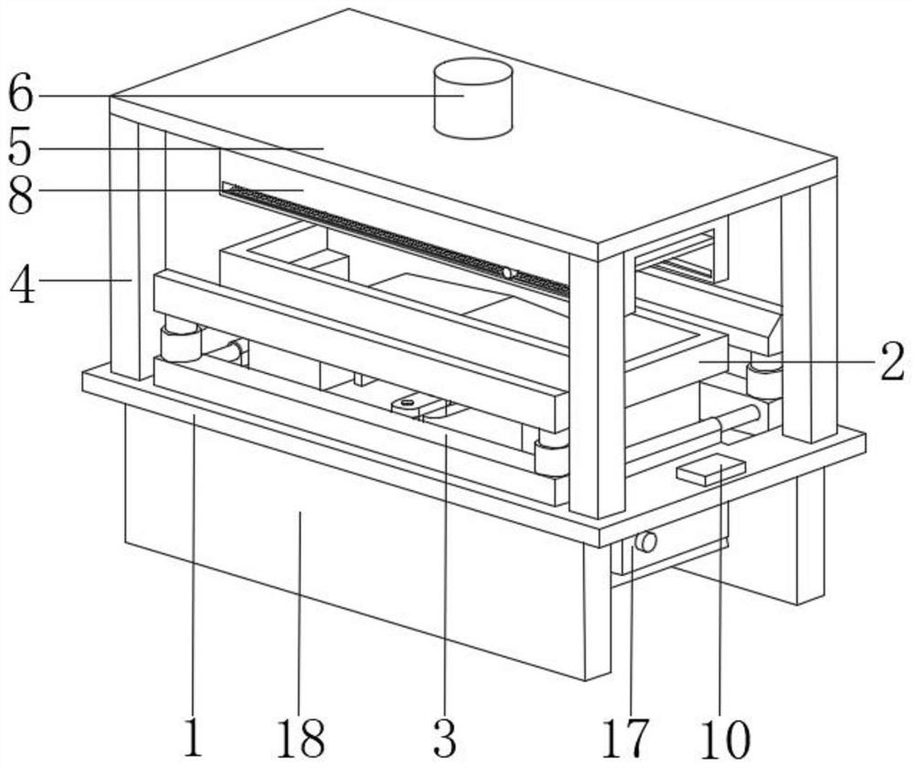
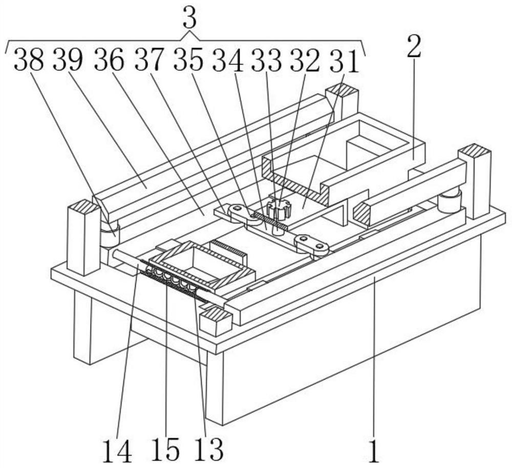
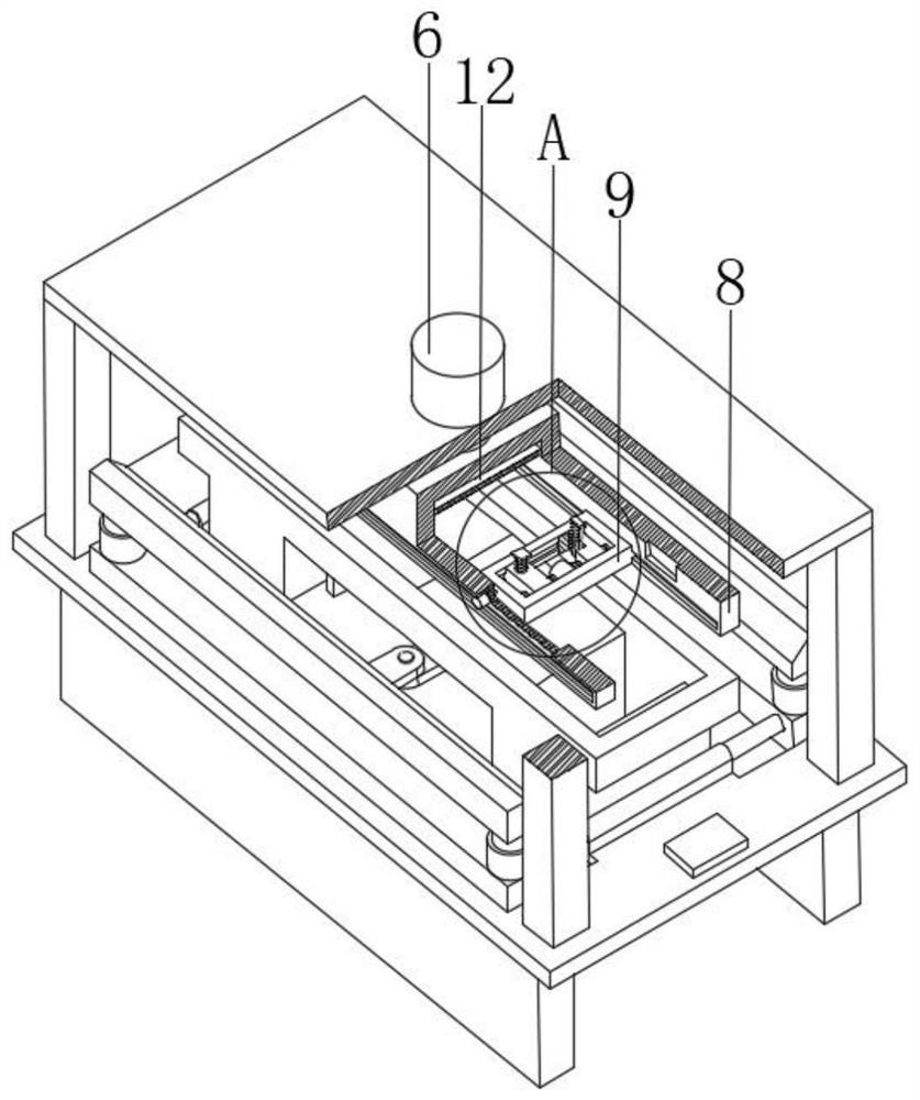
[0028] see Figure 1-5 , the present invention provides a technical solution: an adjustable punching and folding processing integrated machine for cable trays, including a working pallet 1, a bending structure 3 and a punching structure 9;

[0029]Working platform 1: openings are symmetrically arranged on the left and right sides of the upper surface, and the middle part of the upper surface of the working platform 1 is provided with a bridge placement platfor...


PUM


Abstract

The invention discloses an adjustable punching and folding processing integrated machine for cable bridge, which comprises a working platform, a bending structure and a punching structure; There is a bridge placement platform in the middle. The interior of the bridge placement platform is a hollow structure and the openings at the bottom of the left and right sides are respectively connected with the corresponding openings on the left and right sides of the upper surface of the work platform. The four corners of the upper surface of the work platform are symmetrically provided with pillars. The top of the top is fixedly connected with the bottom surface of the top plate, and a hydraulic pump and a hydraulic telescopic column are installed in the installation port at the center of the top plate, and the oil outlet at the bottom of the hydraulic pump communicates with the oil inlet at the upper end of the hydraulic telescopic column; the adjustable cable tray The punching and folding processing integrated machine can press and fix the cable tray to prevent the deviation of the cable tray during the processing process from affecting the processing quality. It can also effectively bend the cable tray and adjust the two-way spacing of the punching holes.

Description

technical field [0001] The invention relates to the technical field of cable bridges, in particular to an adjustable punching and folding processing integrated machine for cable bridges. Background technique [0002] The rigid structural system with close support cables composed of trough-type, tray-type or step-type straight sections, bends, tees, four-way components, brackets, hangers, etc. is called a cable bridge. The cable bridge is divided into trough type, Tray-type, ladder-type, grid-type and other structures are composed of brackets, supporting arms and installation accessories. The bridges in buildings can be erected independently or attached to various buildings and pipe gallery supports. It should reflect the simple structure. Beautiful appearance, flexible configuration and convenient maintenance. All parts need to be galvanized. If the bridge frame installed in the open air outside the building is near the sea or belongs to the corrosion area, the material must...

Claims


Application Information

Patent Timeline
Patent Type & Authority Patents(China)
IPC IPC(8): B21D7/024B21D28/04B21D28/24B21D28/34B21D43/20
CPCB21D28/243B21D28/34B21D28/04B21D7/024B21D43/20
Inventor 刘洋
Owner 江苏中顺电气有限公司
Why Eureka
Try Eureka